 Last November I posted about electronics “shortcuts” — rules of thumb that help interpret, even design, a circuit. These are approximations of more complex behavior but work well enough for a first cut at understanding a circuit.
Do not confuse these electronics shortcuts, which are generally good, with electronic short-circuits, which are almost always bad. While both offer shorter paths, that’s not a good thing in the latter case. Sometimes the journey is the only reward.
I intended to continue with op amps but kept putting it off. There are other Sidebands pending, though, so it’s time to drop the other shoe.
Two things lurk behind my procrastination. Firstly, diagrams. I need a bunch of them; they’re instrumental to understanding. It’s a double pain because I have to design them, and then I need to create them (and I only just now loaded my ancient graphics package onto my new-ish HP laptop).
The second impediment is the topic itself. There are entire books about op amps. No doubt websites and YouTube videos, as well. The trick for me is to stick to the shortcuts theme and to the original circuit that caught my eye and inspired these two posts.
On top of that, I’m a little fuzzy on my audience. I want to keep things simple enough that an interested reader with no background can keep up, but obviously electronics design shortcuts are mainly of interest to those already working with electronics. Ultimately, as usual, I’m writing to amuse myself — documenting something I’ve found interesting and helpful but which I haven’t seen elsewhere.
So, for whatever it’s worth:
§

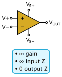
Fig 0. An op amp circuit symbol. Two inputs (left), one output (right).
The first post left off with operational amplifiers (“op amps”). These are multi-component devices (comprised of many transistors and resistors in a single package).
Functionally, op amps are (analog) differential amplifiers. They amplify the difference between two inputs. As such, they have special utility with balanced line transmission.
The trick with op amps is three idealized properties:
- Infinite gain
- Infinite input impedance
- Zero output impedance
See the previous post for details. The shortcut is assuming an op amp, in typical designs, tries to keep the voltage difference at the inputs as close to zero as possible.
The only thing an op amp controls is its output, so the shortcut effectively says that an op amp, in most circuits, generates whatever output makes the difference between the inputs nearly zero. (There is an application, a comparator, that doesn’t do this. I’ll come back to that.)
§ §

Figure 1. Voltage follower.
Let’s start with the simplest possible configuration, a voltage follower — so called because the output voltage “follows” (matches) the input voltage (Figure 1).
The signal enters at the left (E-in) and exits at the right (E-out). Note how the output wraps around to the [–] input. That locks that input to the output voltage via negative feedback.
In an op amp, a tiny voltage difference between the inputs results in a large output voltage. If the [+] input is more positive than the [–] input, the output is positive. If the input voltage is reversed, [+] negative compared to [–], the output is negative. Op amps have “infinite” gain, so if the output is some reasonable voltage, the difference between the inputs has to be almost zero.
With one input locked to the output voltage, the only way to make the differential input almost zero is for the output to match the input. The circuit is designed to allow that.
Start by imagining everything at zero voltage. There is no voltage difference at the input, so the output is zero, which forces the [–] input to zero. So long as the input voltage is zero, the circuit is stable with an output voltage of zero.
If an input voltage makes the [+] input positive, the output also becomes positive. The larger the input difference, the larger the output (“infinite” gain, remember). This pulls the [–] input also positive, which reduces the voltage difference. If the input voltage makes [+] negative compared to [–], the output is negative, but the same logic applies. Either way, the output voltage “follows” the input voltage.
The balance point, which the circuit obtains almost instantly, comes when the output, and hence the [–] input, is just an “infinite” sliver below the input voltage. That sliver being amplified to essentially the positive input voltage. Minus the very tiny difference due to the op amp’s real-world very high gain. In a sense, op amp logic works backwards. The output voltage is the result of minimizing the difference between the [+] and [–] inputs.
§

Figure 2. Same thing.
For the circuit in Figure 1 to work, it’s critical the output wraps around to the [–] input, because this allows negative feedback, which balances the circuit.
If we reverse the inputs (as in Figure 2) now the circuit has positive feedback, which causes runaway behavior because now the “infinite” gain works to unbalance the circuit.
Start again by imagining everything at zero voltage. So long as the input remains at zero volts, the circuit in Figure 2 is stable, and everything remains as zero volts.
But if [–] input goes positive, this drives the output negative (because zero at [+] makes it more negative than [–]). This makes the [+] input even more negative, which increases the voltage difference, which makes the output larger, and so on until the output is pegged at maximum voltage. Note that even if the input voltage returns to zero, the output remains at maximum because the output keeps the [+] input at that maximum.
And if the input voltage makes the [–] input negative, the output goes positive, but otherwise it’s the same story. The output pegs and locks at maximum voltage.
Such a circuit might be helpful if one wanted to trap a transient voltage spike and especially helpful if the polarity of that spike mattered, but I’ve never seen it actually used. The takeaway here is mainly to be sure to keep the [+] and [–] input straight!
§
One might question the value of merely duplicating a signal — same voltage out as in. One might imagine the usual cases involve amplifying a signal or perhaps processing it in some clever way. One would be correct. Usually. But there are at least two important exceptions.
The most common involves an input signal with reasonable voltage (E, energy) but very weak in terms of current (I, intensity, number of electrons). We call the source of such a signal “high impedance” because the inability to provide lots of electrons manifests as high resistance. Recall Ohm’s Law (see previous post). High resistance means high voltage drop. That means high signal loss.
But Ohm’s Law also says voltage depends on current, so if we can keep the input signal current low, we don’t get so much signal loss. Op amps (ideally) have infinite input impedance, so (ideally) draw no current. So (ideally), there is no voltage drop in the input signal.
The (equally ideal) zero output impedance of op amps, in contrast to the weak signal situation, means the next stage has no worries about the signal. Voltage followers buffer a weak signal for other equipment (that may lack the high input impedance of op amps).
The second value of signal following is a bit more esoteric and involves a bit of additional circuitry. There won’t be room in this post to get into it (maybe in a future post), but that additional circuitry is the same as in the two circuits below. It allows us to go from following the input to amplifying it.
§

Figure 3. Amplifier circuit.
The circuit in Figure 3 works roughly the same way as the voltage follower in Figure 1. But rather than a direct path from the output back to an input, the output voltage has a path to ground through resistors R1 and R2, and the op amp’s [–] input connects to the midway point between the resistors.
(The two resistors are the “additional” circuitry.)
This configuration means, rather than seeing the output voltage, the [–] input sees a proportional fraction that depends on the values of R1 and R2.
If R1=R2, then the output voltage is split evenly between them, so the op amp input sees half the output.
When the op amp has an input voltage on the [+] input, to stay sane it must minimize the difference on the inputs to almost zero. Since the [–] input sees only half the output voltage, making that equal the input signal requires doubling the output voltage.
So, when R1=R2, the circuit amplifies the input by a factor of two. When R1 is larger than R2, amplification increases accordingly. If R1 is 99 times R2, the amplification factor is 100. [To figure the factor: (R1+R2)÷R2]
Note that in terms of gain, the worst this circuit can do is zero (unity). That happens when R1=0 — which emulates the direct connection from output to input used by the voltage follower above. (R2 then becomes irrelevant except for adding a current load to the output.)
§
Rearranging the circuit (see Figure 4 below) allows negative (as well as zero or positive) gain.
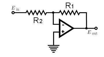
Figure 4. Another amplifier circuit.
Now the [+] input is tied to ground, fixing it at zero volts. Here the op amp wants the voltage on the [–] input to also be (almost) zero.
To do that it must produce an output voltage opposite in polarity from the input. Then E-out cancels E-in, producing zero where they meet in the middle.
Again, the ratio of R1 to R2 controls the gain. The larger R1, the larger the gain. In this circuit, however, gain is zero when R1=R2. Then the voltage drops are equal, so the output matches the input except for reversed polarity. If R1 is smaller than R2, the gain is negative — the output is reduced compared to the input (it’s rare that a situation calls for this).
And as with the voltage follower, keeping the [+] and [–] inputs straight is important. If they’re swapped, the circuit demonstrates runaway latching behavior.
§ §
All this follows from the three basic op amp rules along with the operational consequence of the inputs at nearly the same voltage (whatever that voltage might be). Unless the voltage difference at the inputs is very tiny or zero, the op amp loses its mind.
Which brings us to the obvious question of what happens when the circuit, or input, doesn’t allow the op amp to equalize the inputs? How does it lose its mind?
It’s implicit in the first rule. The “infinite” gain means any noticeable input difference gets amplified to a huge output voltage. But the power supply limits how high that can be, so the op amp “pegs the needle” or “maxes out”. It makes the output as large as the power supply allows.
Which is a normal operational mode for op amps: comparator mode. In these, we don’t include feedback from the output; we want to op amp to peg. Generally, we tie one input to a reference voltage and the other to the input or sensor.
One use is converting an analog signal to a digital one by comparing it to a threshold voltage. When the signal is above the reference, the comparator outputs a “1”. When it’s below, a “0”. Comparators are also useful when a sensor voltage varies within some allowed range but must generate an alarm if it crosses a threshold voltage.
§
It’s important to emphasize that op amps are voltage devices. No current flows into their inputs (infinite input impedance), they only care about the voltage difference between the [+] and [–] inputs. And that voltage difference needs to be practically zero for the output to not be maxed out.
Linear operation depends on a circuit with feedback. Then the output voltage depends on the input differential.
Current is relevant only because the “zero” output impedance means the op amp provides as much current as the next stage draws. Unless the op amp has over-current protection, drawing too much from the output can damage the device.
Bottom line, op amps are easy to understand. The inputs float, no current flows into them, and the output doesn’t get bogged down unless the circuit is really bad. Assume infinite gain and that’s pretty much the ballgame.
§ §
Which brings me to the simple circuit that inspired these articles, a current-to-voltage converter (see Figure 5 below).
First time I saw one (while researching SPADs), there was a moment of, “Huh?” quickly followed by a moment of “Ah!” (thanks to the three rules of op amps, and that made me think I should pass them on).

Figure 5. Current to voltage converter.
This works a little bit like the amplifier in Figure 4, but R2 and the input are replaced by a current source (I). The hexagon is some kind of very sensitive detector (such as a SPAD) that outputs a high impedance low current signal. Just a handful of extra electrons; no real voltage to speak of.
Note the op amp’s [–] input is tied to ground, which locks it at zero volts. We know the op amp therefore wants to keep the [+] input at (almost) zero, too.
When the detector is idle, no electrons flow, and everything everywhere is at zero volts. Output is zero, so nothing flows through R1.
When the detector pumps some electrons into the circuit, they have to go somewhere. They can’t flow into the “infinite” impedance op amp input, so they have to flow through R1. Ohm’s Law says the voltage across the resistor is current times resistance, so even that handful of electrons generates a voltage across the resistor.
Since the op amp wants the left end of the resistor kept at zero, it has to make the output positive. The voltage depends on R1 and how much current the detector supplies. As a reference, a current of one microamp through a one-megohm resistor generates one volt.
The op amp, with “zero” impedance output, provides a strong definite signal at a convenient voltage. Thus, researchers can connect a sensitive detector with a faint output signal to recording equipment that expects more normal signals.
§ §
Stay op amped, my friends! Go forth and spread beauty and light.
∇


September 9th, 2022 at 9:38 am
I know all my readers have been anxiously awaiting this continuation post! 😉
September 9th, 2022 at 9:59 am
But at least now I can move on to other Sidebands. 👨🏼💻😎
September 26th, 2022 at 4:59 pm
Ugh! I’m glad no one reads these. I just noticed the [+] and [–] inputs in Figure 5 are reversed. D’oh!
As with the other circuits in the post, reversing the inputs causes a meta-stable zero point, but any input (in this case any electrons from the current source) throws it into positive feedback and pegs the output.
June 1st, 2023 at 11:27 am
[…] they’re very cool but also easy to understand in the context of the Three Rules of Op Amps. [See this post and maybe the one before […]