 In the first part of this series I touched on the evolution of (landline) telephone switching — which began with operators handling calls manually and which ultimately became the job of computers.
One of the last stages along the way was an electro-mechanical relay-logic marvel of unsurpassed engineering complexity, the #5 Crossbar Switch.
The last post introduced the switch fabric through which calls are routed. This post explores how that fabric is controlled and what happens when we pick up the phone, dial it, and are connected to the remote end.
As we saw last time, the switch fabric for a #5 Crossbar Switch consists of four layers, each with multiple individual 10×10 crossbar switch units.
[Terminology note: The term crossbar switch refers both to the individual 10×10 units and the entire switching system based on those units. I’ve tried to make clear in context which I mean, but I also capitalize Crossbar when I mean the entire switching system.]
This switch fabric is nothing more than wires and connection points (switches) where closing a series of connections provides a path through the fabric. There is no logic in the fabric itself, just potential paths.
This fabric is monitored and controlled by an extremely intricate relay-logic system known as a marker. [For more on relay logic, see SB#61: Tock.]
A marker typically contains thousands of relays implementing the logic.
[Walking down the aisles of a Crossbar switch, the most notable thing is the constant chattering of those thousands of relays.]
Describing how markers operate is a formidable task given their complexity, and it’s one I’m not qualified to write about in great detail. I will only here try here to describe the basics (as I understand them).
To provide some flavor of the complexity, here is one page of the 38 wiring diagrams for what is formally called the link, link, and marker circuit:
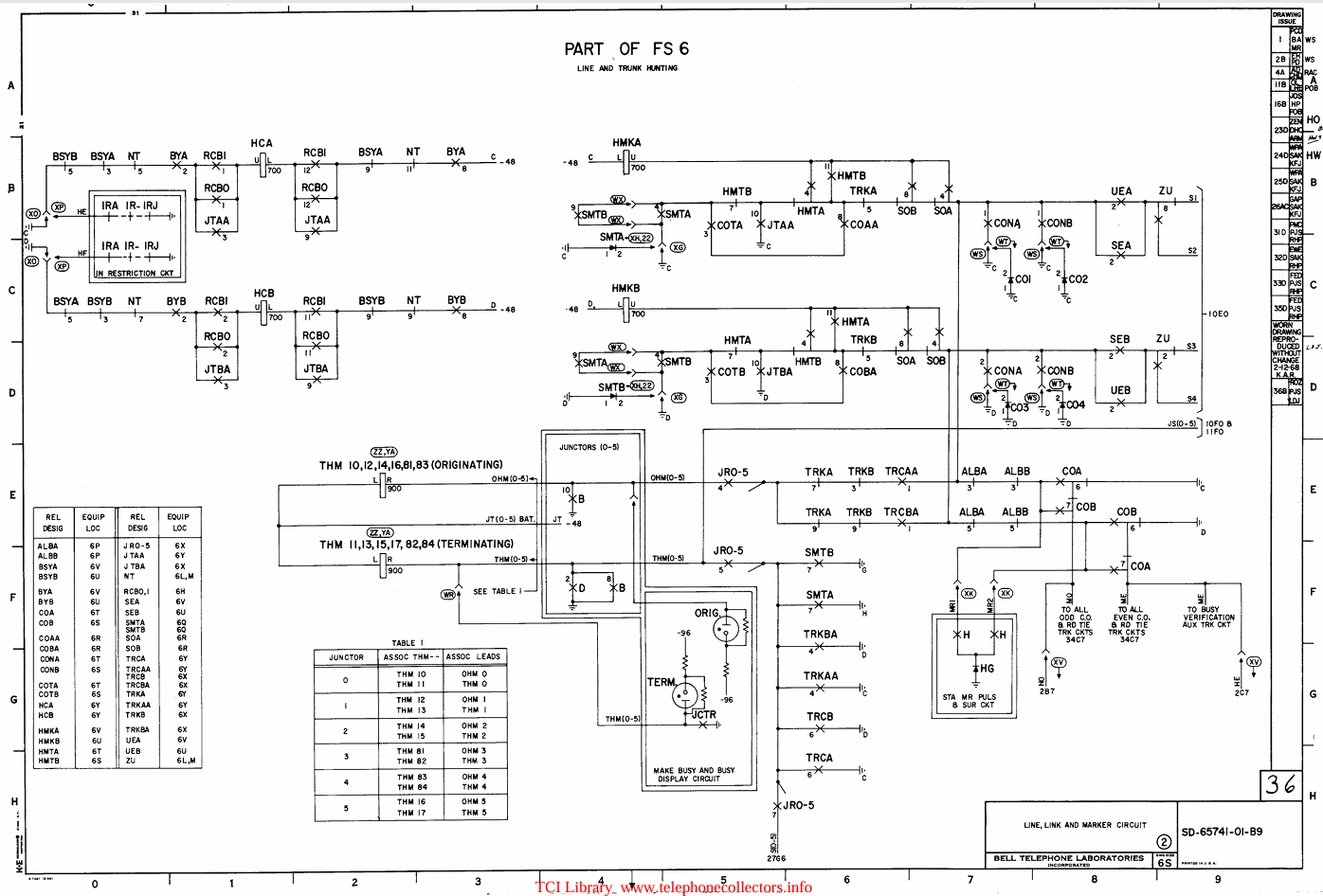
The PDF file this came from has 104 pages; the other 66 pages are tables, part and options listings, process flowcharts, and example diagrams illustrating specific situations.
[I got the PDF file from this site (though I can’t locate the actual document I downloaded a few years ago). The content of the PDF looks very similar to the book of wiring diagrams I had decades ago.]
Let’s dig into a tiny bit of the relay logic involved. Below is a small section (the upper left corner) of the above diagram:
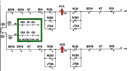
Two relays, labeled HCA and HCB (Hunt Connector A/B), are highlighted in red. These diagrams use rectangles to indicate relays and, as in any schematic, lines to represent wires. Note the redundancy. The upper and lower parts are identical and act in tandem.
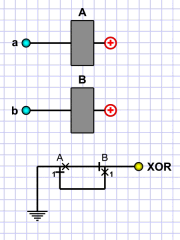 The marker has error-detection circuits to detect if the two do not operate identically. These use one set of contacts from each relay (HCA and HCB in this case) wired in an XOR configuration.
In the simplified diagram to right, if the relays A and B do not operate in tandem — either both active or both inactive — the output (labeled XOR) provides a ground path to an error-detection circuit that activates an alarm indicating a problem in the marker.
Returning to the section above, the part outlined in green is from another circuit but repeated on this diagram as helpful information. The circled letters, XO and XP, represent wiring options. Which is used depends on local requirements.
The short single lines and crosses along the wires are relay contacts (labeled with the relay they belong to and a number indicating which contact set). The single lines are break contacts; the associated relay must not be active for current to flow. The crosses are make contacts; the associated relay must be active for current to flow.
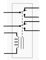 This is rather different from standard schematics, which use a less abstract symbol for the relay (usually depicting its coil of wire) and its contacts (see diagram to the right).
Furthermore, relay contacts are generally drawn adjacent to the relay symbol, usually with a dotted line from the relay to the contacts.
When I first got those line, link, and marker schematics (back in the 1970s), it took me a while to figure out that the rectangles were the relay coils and the lines and crosses along the wires were their contacts. But it makes sense. In a complicated system like this, keeping the contacts and relays together would turn the wiring diagram into an unreadable mess.
If we look at the upper half (the lower half is essentially the same), we see a ground connection on the left and a -48 volts connection on the right. The line from ground on the left, through the relay, and to -48 volts on the right is interrupted by multiple relay contacts, some make, some break.
This forms a chain of logic. For the relay to activate, we need (from left to right):
BSYB, BSYA, NT must be inactive; BYA must be active; and one (or more) of RCB1, RCB0, or JTAA must be active. The contacts on the right repeat the ones on the left. Together, this comprises a logical expression:
HCA = ~(BSYB|BSYA|NT) & BYA & (RCB1|RCB0|JTAA)
To help understand what the relays do, there are tables providing the functional names of relays in the marker. The one below lists key relays in the marker circuit:
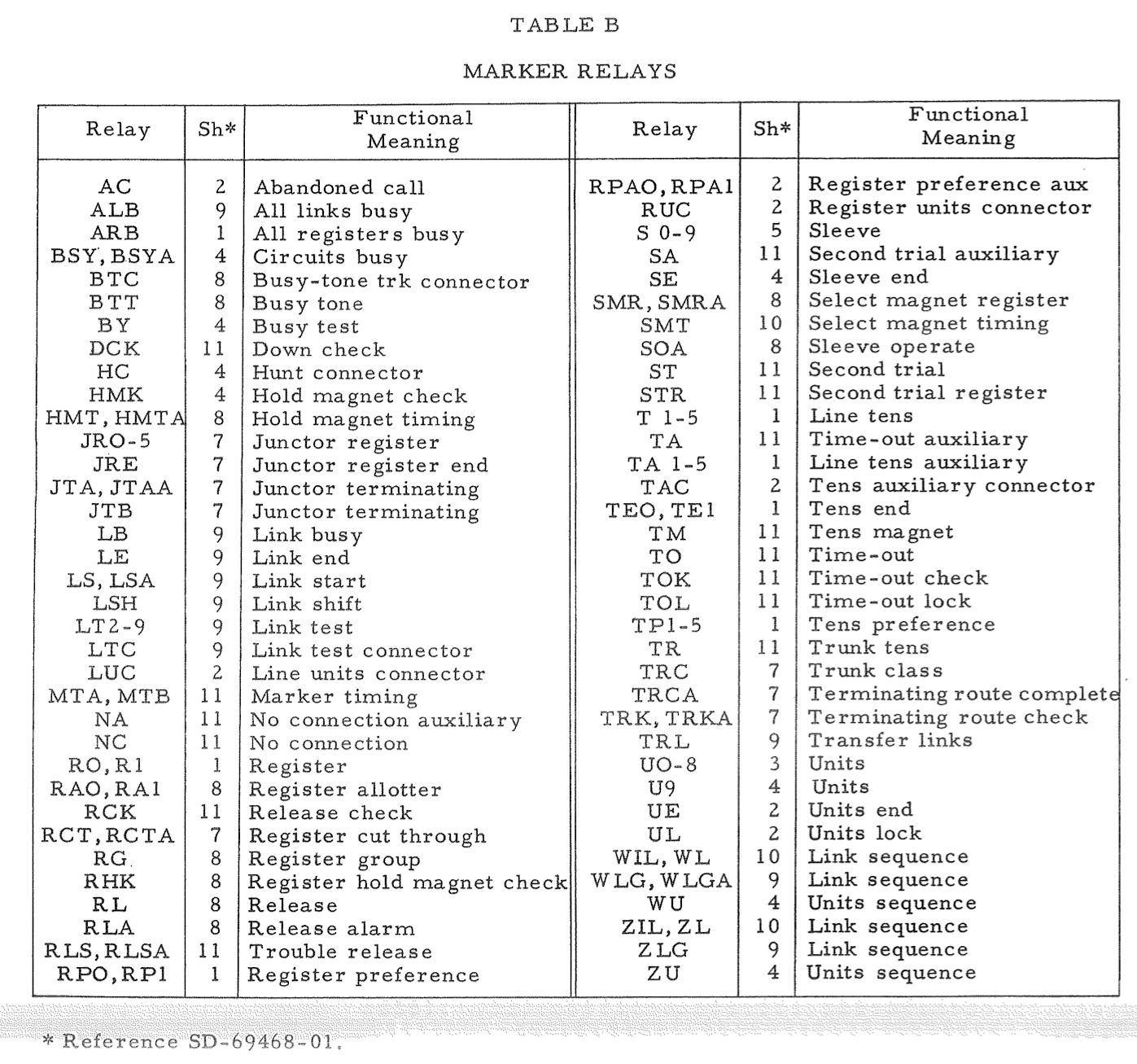
The column labeled Sh* lists the sheet number (from the book of schematic diagrams) on which the relay coil is located. As we’ve seen, the relay contacts can be anywhere they are needed.
§
The marker’s job is to monitor the system and create and release paths through the switch fabric. There are essentially three fundamental situations the marker must handle:
- Subscriber picks up the phone to make a phone call. The marker detects this and provides a path to a dial register circuit that provides dial tone and accepts the subscriber’s dialed digits.
- The subscriber has dialed a valid number, and now the marker must release the path to the dial register and provide one to a trunk circuit to connect the subscriber with the dialed number.
- An incoming call from a trunk must be connected to the dialed subscriber line. Once the path is established, the trunk circuit rings the subscriber and detects whether the subscriber answers.
These three comprise the steps of a regular completed call. There are a variety of other things a marker must handle. For example, the called subscriber’s phone may be off hook, so the marker must provide a busy signal to the caller. Less commonly, all the trunk circuits to the called number might be engaged, so the marker must provide a busy trunk signal to the caller.
Dialing a Number
When we pick up the receiver on a landline phone, this closes a switch in the phone, and current can flow through the local loop.

Recall that the two wires comprising the loop are known as tip (usually green) and ring (usually red). These wires are formed as a twisted pair to reduce interference.
The loop begins and ends at the local central office (CO), which is often a non-descript building discretely located in the neighborhood it serves. There are practical limits on how long a local loop can be, so central offices are scattered throughout neighborhoods. (If you keep your eyes open while walking or driving around, you may spot one. They’re often small buildings with few or no windows and a single very locked door.)
Each loop ultimately terminates in a line circuit:
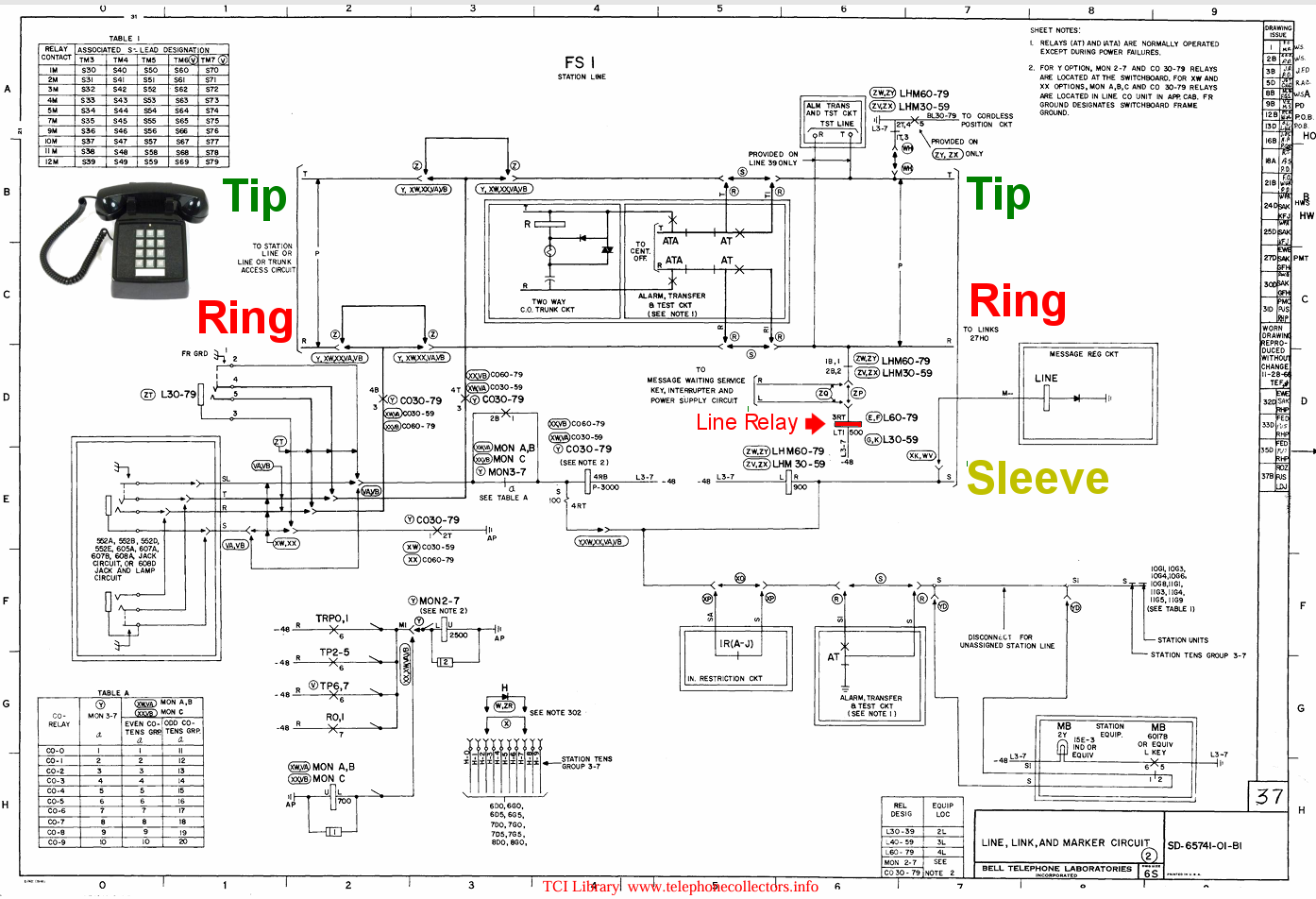
The tip and ring wires from the local loop enter the diagram at the upper left. They, along with the sleeve line generated by this circuit, proceed into the switch fabric from the upper right.
[This diagram is complicated because of all the options available for different types of phone line configurations.]
Most importantly, note the line relay (highlighted in red). The current flowing through the local loop (because we picked up the receiver) activates this relay, and that informs the marker that we intend to make a call.
Alternately, if our phone is being rung for an incoming call and we pick up the receiver to answer that call, this also activates the line relay, which informs the marker we answered.
In the first case, where we pick up the receiver to make a call, the marker finds an available path through the switch fabric to a dial register circuit:
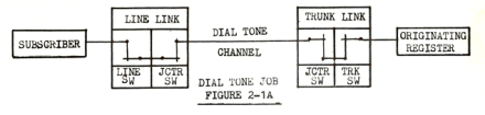
There are a number of these (formally called originating registers), the exact number depending on how many subscribers the switching system handles.
An important characteristic of the #5 Crossbar Switch is that how the marker establishes a path through the switch fabric is the same as when it connects a call. Symbolically, we can think of all the subscriber lines handled by the switch as being on the left and all possible connections (trunks, registers, and others) as being on the right.
So, the path to the register looks very similar to the paths made for outgoing and incoming calls:
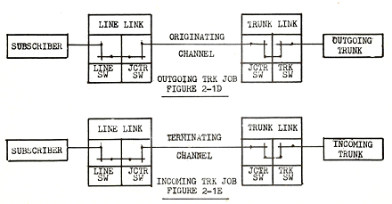
In fact, the marker uses the same path-finding logic in all cases. The only thing that varies is the actual subscriber line and the actual trunk (recall that dial registers are a special type of trunk circuit).
For completeness, here is an intraoffice connection:
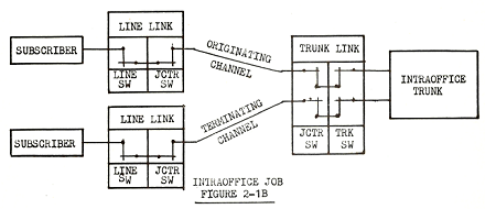
Such a call requires two paths through the switch fabric. I would imagine that these days such calls are fairly rare. How often do we call a number that shares our prefix? (For example, how often does a subscriber with the number 555-3921 call another number with a 555 prefix?) The one place such calls would be common is within a company PBX when one employee calls another.
Getting back to making a call, here is a diagram showing the marker relays that activate (or inactivate) as the marker routes the subscriber through the switch fabric to the register:
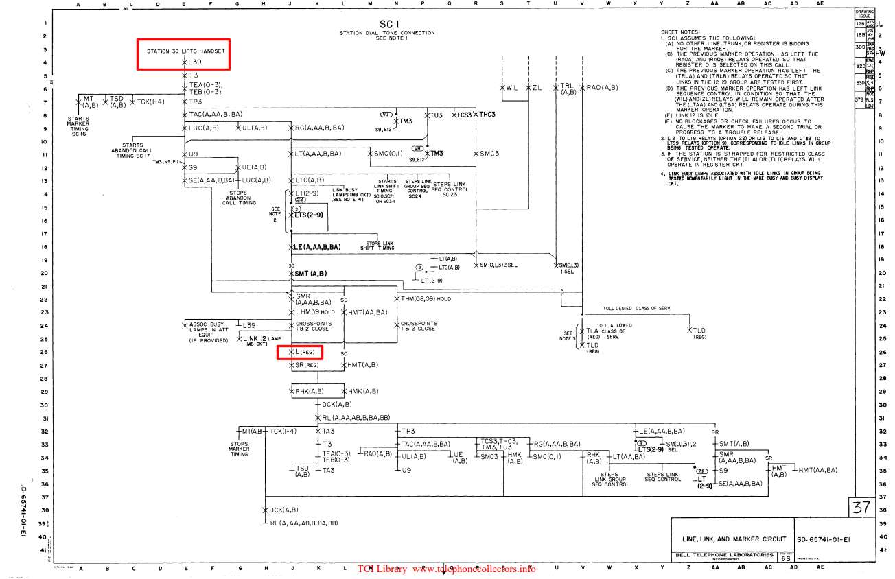
The red box in the upper left is where line 39 picks up the receiver, which actives the associated line relay, L39. This activates T3 (Tens-3), which actives TEA and TEB (Tens End), and so on.
The red box in middle is where the connection through the fabric terminates at the register, thus activating its line relay. Various relay activations and releases below that point are the marker releasing the various relays involved.
At this point, the subscriber is connected to the dial register. Which sends dial tone to the subscriber to indicate its readiness to accept (and decode) dialed digits.
 Originally, phones used rotary dials for dialing. These generate a series of specially timed interruptions (“pulses”) in the local loop — the number of which depending on the digit dialed.
If we dial a 4, that creates four interruptions. (The interruptions occur after we release the dial as the dial returns to its home position.)
This is formally known as pulse dialing.
Some places would put a little lock through the digit 1 hole that prevented dialing the phone. But if you knew how dialing worked — just the necessary number of interruptions — you could dial a number by repeatedly pressing the switch hook to interrupt the circuit. You had to get the timing right, but dial registers are fairly tolerant.
You may have seen this done in movies where a character has access to a phoneline but, for whatever reason, has no ability to dial. (Kim Basinger does this in the 2004 thriller Cellular.)
In more modern times, phones use “touch tones” for dialing. This is formally known as DTMF signaling (dual-tone multi-frequency; each digit consists of two different tones). Modern registers still handle pulse dialing, though.
Registers also handle timeouts, where the subscriber dials no digits or starts to dial and doesn’t finish. When this happens, the register signals the marker, which releases the path to the register (so it can handle other subscribers) and creates a new path to a special trunk that provides the off-hook timeout signal.
Registers also have to deal with invalid numbers — dialed digits that don’t conform to a valid phone number format. Here again, the register signals the marker, the marker releases the register and connects the subscriber to an “invalid number” trunk (usually a recorded message).
Connecting a Call
Assuming the register receives a valid number, it decodes the number to determine the destination information and passes that to the marker. Which releases the path between subscriber and register. The marker uses the info to determine what kind of trunk is required to complete the call. If the called number:
- Has the same prefix, the marker finds a path to an intraoffice trunk as well as a path from that trunk to the called subscriber. The intraoffice trunk provides both the ringing signal to the called phone and the ring-back signal to the caller (which indicates the called number is being rung).
- Has a different prefix, the marker finds a path to an interoffice trunk that connects to a remote CO. In many cases, that trunk circuit leads to a tandem office that routes the call to other tandem offices or to the destination CO.
- Has an international prefix, the marker finds a trunk circuit that leads to a CO that handles international calls.
- Is special, such as 411, 911, 0 for operator, the marker routes to trunks that handle such connections.
In all cases, from dialing to connection, the marker’s path-finder logic is essentially the same. It knows the subscriber and trunk, so it tries to find an available path through the switch fabric to complete the connection. Or drops the subscriber into an appropriate error signal if it can’t. For all its complexity, the basics are fairly simple.
Here is an architectural diagram of a #5 Crossbar Switch:
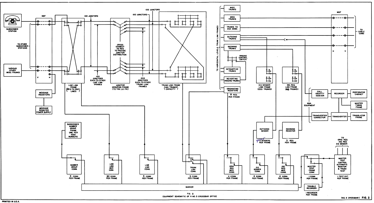
One thing to note is that the marker logic (bottom long rectangle) connects to the switch fabric and various trunk and line circuits through a series of large relays. This is because there are typically multiple markers per Crossbar Switch, and they only connect to the other components when they need to act on them.
§ §
That’s enough for this time. Next time I’ll get into the very interesting way that crossbar switches work.
Stay switched, my friends! Go forth and spread beauty and light.
∇


April 24th, 2026 at 10:14 am
[…] of telephone switching and introduced the switch fabric comprised of many 10×10 crossbar switches. The second post discussed the line and marker circuits; the latter of which implements the switching […]