 My fascination with relay-controlled systems begins in the mid-1970s when I stumble on two sets of bound documents for the PBX in an office that went out of business. The ledger-sized one (17″×11″) had circuit and logic diagrams; the page-sized one (8½”×11″) had descriptions of the diagrams and PBX operation (see SB #61: Tock for more).
I spent many hours studying those books but only ever figured out the basics. These telephone switches are among the most complex electro-mechanical machines we’ve designed.
This series of posts explores this last species of telephone switch controlled entirely by relay logic: the #5 Crossbar Switch.
It’s a little weird that I’ve waited almost 15 years to write about one of my favorite topics. In large part because writing about it requires diagrams, lots of diagrams, and creating those has been a slow (on and off) process. Figuring out what and how to illustrate what I want to explain took a lot of time. Let alone getting around to actually making them.
There is also figuring out how to tackle a complex topic that has bookshelves of documentation associated with it. As I said in the intro, these machines are among the most complex (electro-mechanical devices) we’ve ever designed.
All for the quotidian task of completing phone calls. (Back in the days of land lines. Things are much more complicated with mobile phones and data, but computers handle it all with ease. For some definition of “with ease”.)
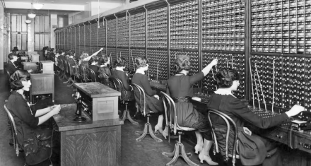
It started (once telephones existed) with operators. To make a call, you had to signal the operator and give her the number you wanted. She (almost always she in those days) manually rang the other end and connected the call if the remote end picked up the phone. She also “supervised” the call and disconnected it when it was over.
An irony of telephony is that in the first days of its invention, no one thought it would be important. The prevailing belief was that no one would want to talk to someone who wasn’t actually present.
But the telephone arguably turned out to be one of those culture-altering revolutions (one that continues to evolve).
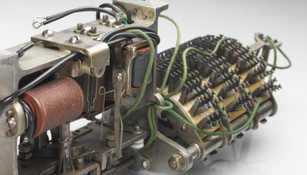
The step-by-step switch (aka the Strowger switch) was patented in 1891 by an undertaker unhappy with manually switched calls (his thought-to-be defective phone installation caused him to believe the operators were interfering with his calls, and he vowed to put them out of a job.
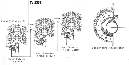
It’s one of the earliest attempts to switch calls automatically. The two-level rotary mechanical switch Strowger invented connected one input to one hundred outputs (or one hundred inputs to one output).
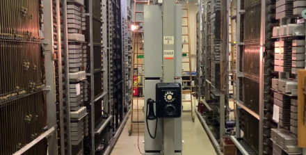
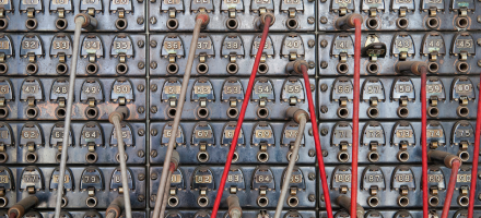
The panel switch, first installed in 1915, was another early electro-mechanical machine that automated the process of connecting, supervising, and disconnecting telephone calls.
In the image above, note the vertical rods on the far left (another set is a bit further back from camera on the right). These are the distinctive feature of panel switches. The rods — driven by motors —slide up and down to connect calls.
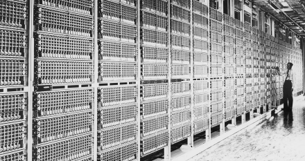
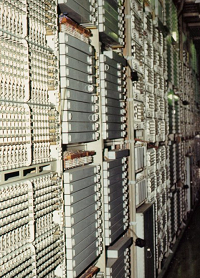
The crossbar switch, first installed in 1938, implemented the network topology of panel switches but without motors and sliding contacts. In their final form, the #5 Crossbar switch, they are the last purely electro-mechanical systems used to switch phone calls. The image above shows racks of crossbar switches — easily identified by their grid-like appearance.
[The next step in switching technology was computer-controlled switching that eliminated the need for relay logic. Modern phone switches these days are entirely computer-controlled. All the logic is in the software now.]
§
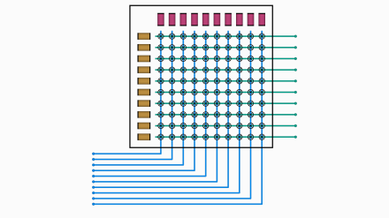
Generically speaking, a crossbar switch is a matrix — let’s say 10×10 — of possible connections between the vertical columns and the horizontal rows. So, our 10×10 crossbar matrix has 100 potential connection points. In these diagrams, the inputs are the blue lines coming from the lower-left and the outputs are the green lines going to the right.
This configuration allows connection of any input to any output by activating one of the one hundred connection points:
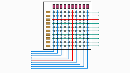
Since there are ten inputs and ten outputs, there is always an available path from an input to one of the outputs:
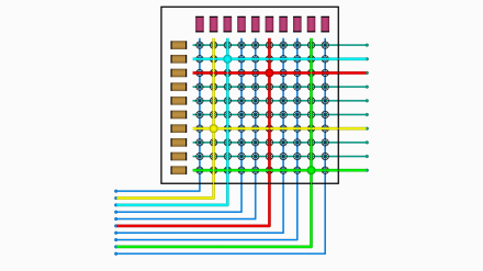
In the example above, four of the ten inputs are connected to four outputs, but the remining six can still connect to the remaining six outputs. If we were to imagine these examples as telephone lines being connected to the switch system, every phone could be in use, no one is blocked.
In reality, not everyone uses the telephone at the same time, so switching systems have the notion of concentration — the ratio of subscriber lines to available paths through the switch.
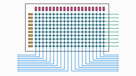
The example above has a concentration of 2:1 because there are 20 inputs (blue lines below) and only 10 outputs. If the inputs are subscriber lines, then only half of them can use the telephone at the same time. If an 11th subscriber picked up their phone, they would find it dead until one of the other ten hung up.
Note that the 20×10 design above is often implemented by wiring the horizontal lines together in a pair of 10×10 crossbars. Higher concentrations can be achieved by wiring a third or even fourth 10×10 crossbar into the circuit.
§
The main thing I want to explore here is the mechanics of the 10×10 crossbar unit. The design is quite clever. A direct approach would require 100 relays, one for each of the 100 connection points.
But 100 relays per 10×10 switch is a lot of relays. And note that, at best, only ten of them would ever be activated — at least 90 of them are always idle. Rather a waste of switching components.
Instead, the design uses only 20 relays: 10 for columns (red rectangles in the diagrams above) and 10 for rows (gold rectangles). It’s the mechanical way they interact to close a connection point that I find so cool.
The gold row relays are called select magnets; the red column relays are called hold magnets. They are called magnets because they aren’t really relays in the usual sense — they don’t, on their own, close any contacts. Rather, they are solenoids that move bars of metal, and the interaction between a horizontal select bar and a vertical hold bar closes the connection contacts.
The basic process of closing a connection goes like this:
- Activate select magnet for desired row.
- Activate hold magnet for desired column.
- Release select magnet (for reuse on other columns).
The connection lasts so long as the hold magnet is energized. If four subscribers are engaged in four phone calls, only the four hold magnets associated with their columns are active on the crossbar.
§
As you’ll see, by using many of these 10×10 switches together, we create a switch fabric for routing calls. The exact design of the switch fabric depends on the number of subscriber lines as well as the expected traffic. The version discussed here handles (in theory) 100 subscriber lines (in fact, typically at least 10 inputs are reserved for testing).
First, though, a few points about how we represent the individual 10×10 crossbar switches comprising the switching fabric.
The diagrams above use a single line to represent the inputs and outputs. In reality, a subscriber line — the connection between the installed telephone and the central office (CO) that handles it — has two wires (known as the local loop because your phone is at one end of a loop of wire):

These are canonically referred to as “tip” (green) and “ring” (red). The terms come from the jacks and corresponding plugs that telephone operators used to connect calls:
These plugs actually have three wires each. A third wire, known as “sleeve” (yellow) is used internally to the switch and serves as a control line within the switching system.
If you ever used stereo headphones with wires, you’ll remember those three-wire plugs:
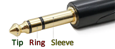
In those, the tip and ring were the left and right audio, and the sleeve was the common ground. In a phone switch, tip and ring are the “talk path” (electrically known as a balanced line) and the sleeve is a control line.
This all means that, despite the single line in the diagrams above, crossbar switches actually switch at least three wires at each crosspoint:
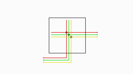
Some designs switch four or six wires each, depending on the system requirements. The typical case, and the one I’ll be discussing in detail here, switches the standard three, tip, ring, and sleeve. Note that the diagram above shows a single crosspoint within the crossbar (one of 100). The red and green wires are the ring and tip lines from the subscriber’s local loop; the yellow sleeve line is implemented by the switch and used internally to monitor the call status. (Specifically, it detects when either side of the call hangs up.)
§
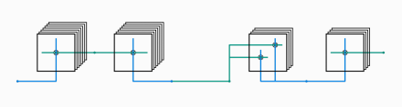
A switch fabric consists of multiple layers (typically four) with multiple crossbar switches comprising each layer. The outputs of one crossbar are distributed to all the crossbars in the next layer:
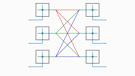
The toy example above shows a two-layer system (the left and right vertical columns) with each layer having three crossbar switches. The six crossbars are represented schematically with a single input and a single output, but these represent the 10 lines in and 10 lines out. In switches with higher concentrations (such as the 20×10 example seen earlier), the single input line may represent 20, 30, or even 40 inputs.
The key point here is that the outputs of each crossbar in the first layer are distributed to all the crossbars in the second layer. This means that any input from any crossbar in the first layer can connect to any output of any crossbar in the second layer (assuming the desired output is not currently in use).
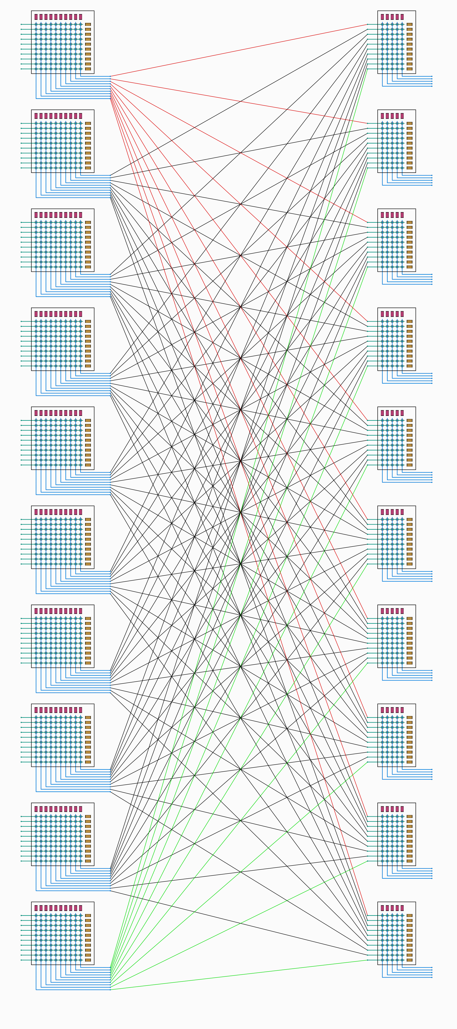
The toy example hides a lot of details. Here’s a real example of the first two layers of a basic system with up to 100 subscriber lines:
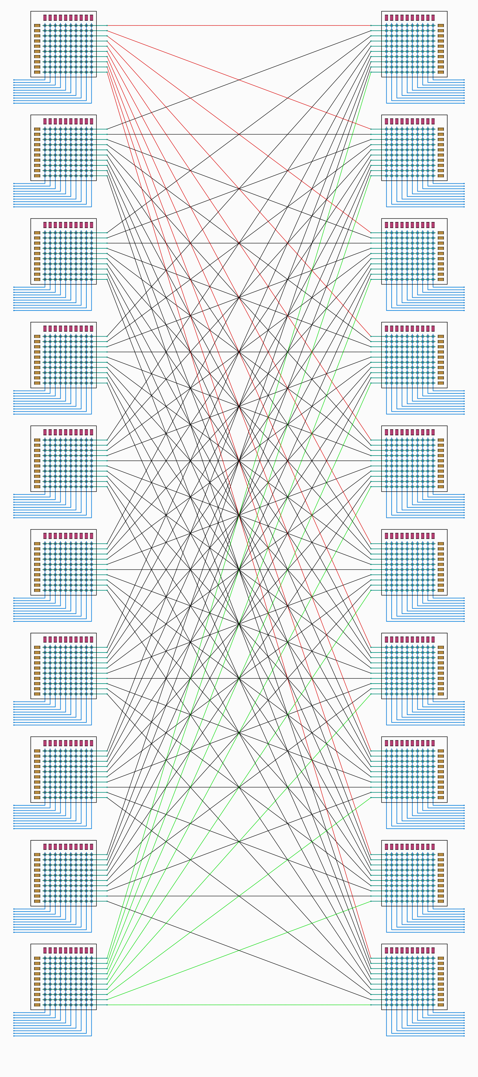
Click the image to see it full size (1600×3600 pixels). Remember that each line is actually three wires, tip, ring, and sleeve. Assuming no paths are currently in use, any of the 100 inputs can connect to any of the 100 outputs.
Most switch fabrics consist of four layers:
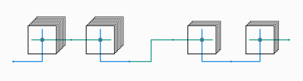
The above is a schematic representation of the four layers. Each layer consists of multiple crossbar units, the exact number depending on the configuration. From left to right, the layers are named:
- Line switches (which connect to the subscriber lines)
- Line-Link switches
- Trunk-Link switches
- Trunk switches (which connect to trunks)
Typically, there will be at least ten crossbars in the Line switch layer (for a 1:1 concentration), but there may be 20, 30, or even 40 with their horizontal lines wired together to allow for more subscriber lines. It depends on the expected traffic. A quiet suburban or rural area with low traffic can use a high concentration, but a busy downtown area may require a lower concentration in order to handle the expected traffic.
Note how, in the first two layers (left), the horizonal lines connect the layers, but in the last two layers, it is the verticals that connect them. Between those, in the middle, are lines called junctors, which connect the vertical lines on the crossbars on the left (the Line-Link switches) to the horizontals of the crossbars on the right (the Trunk-Link switches). This may seem an odd topology, but it has evolved from considerable analysis and experience in call switching.
In fact, the topology is often a bit more intricate than shown:
There is a concentration between the Link-Link and Trunk-Link layers. The Trunk-Link 10×10 crossbars are often electrically split into a pair of 5×10 crossbar switches with just five output verticals connecting to ten horizontal junctor lines. This means only five 10×10 physical crossbars are necessary to concentrate the 100 junctor lines to 50 trunk link lines (which connect the Trunk-Link switches to the Trunk switches).
This concentration means that the switch overall can handle up to half the 100 possible subscriber lines. (And recall that at least 10 lines — one per Line switch — are allocated for testing, so the reality is 90 subscribers.)
As an aside, the junctors that connect the left two layers with the right two layers used to be active circuits that supervised the call and provided the power for both ends of the phone connection. In the modern design, this is handled by the trunk circuits (which we’ll get to), and the junctors are now just wires connecting the Line-Link layer to the Trunk-Link layer.
So, the reality of the junctor wiring looks like this:
Note how the Trunk-Link switches (right) are 5×10. The ten horizontals each get one (vertical) line from the Line-Link switches (left). But each 5×10 represents a concentration down to five outputs from the ten inputs.
Here, then is how the Trunk-Link switches connect to the Trunk switches:
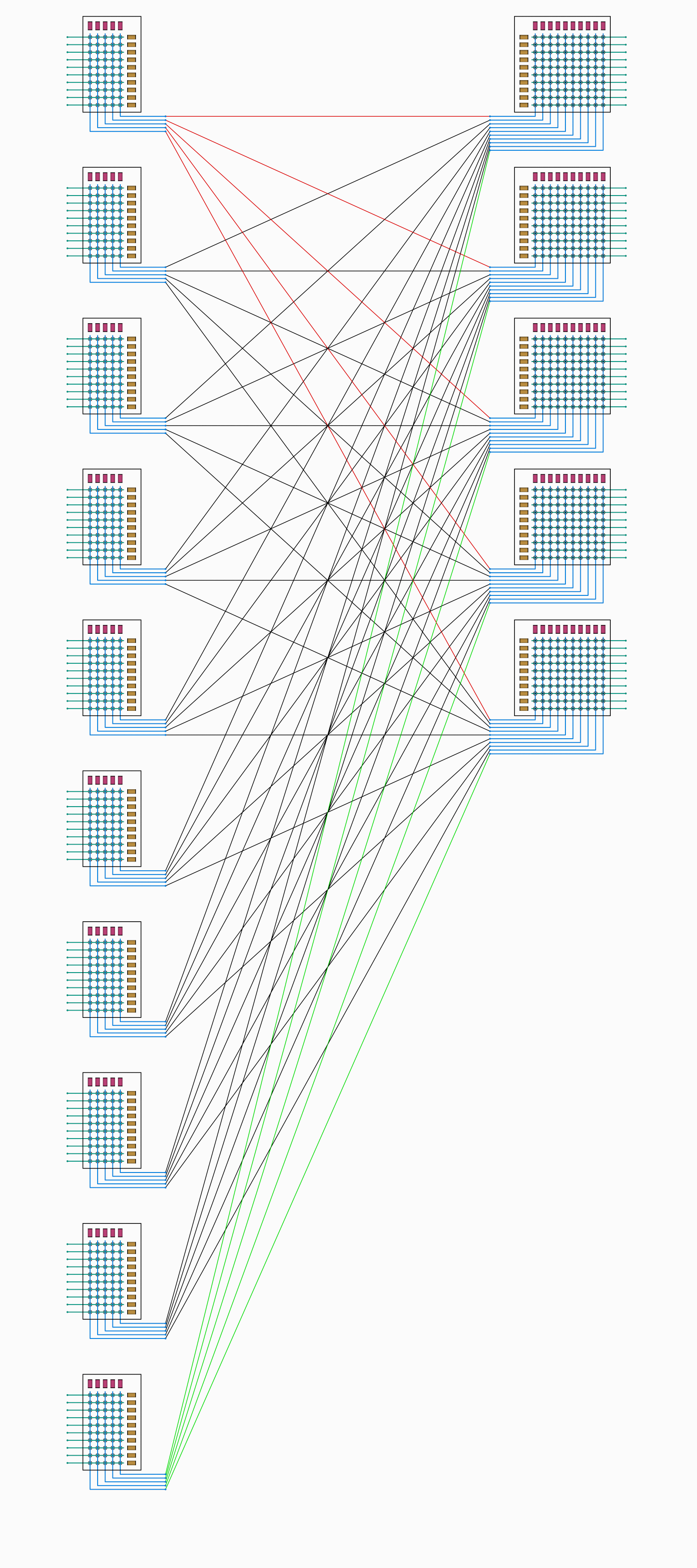
Overall, the 100 possible Line inputs are reduced to 50 possible Trunk connections.
In total, our simple switch fabric looks like this:
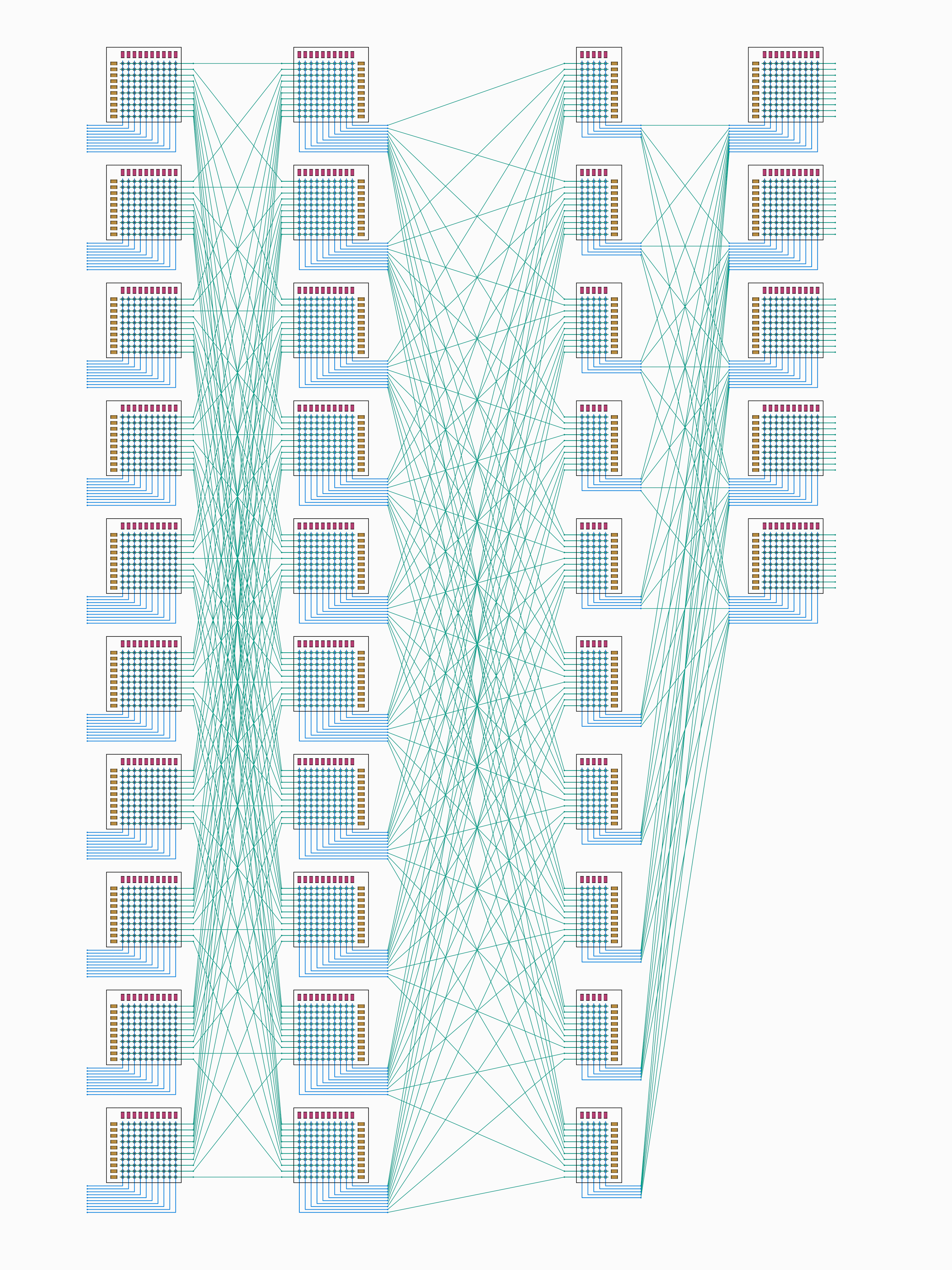
With 100 inputs (nominally subscriber lines) and 50 outputs to various types of trunk circuits. And remember, each line and crosspoint represents three wires: tip, ring, and sleeve.
[Click the various switch fabric images for full-sized versions but be advised they are large. The one directly above has 2700×3600 pixels and is almost four megabytes in size.]
§
This all brings us to an obvious question: What is a trunk?
There are three basic types of trunks:
- Remote trunks
- Local trunks
- Dial Register trunks
A remote trunk circuit is a link to another central office somewhere in the world. When we make a phone call to anyone outside the area serviced by our central office, it’s done over a remote trunk. On the other end, in the central office that services the phone we’re calling, a remote trunk there accepts the incoming call and routes it through its switch fabric to connect with the remote phone. That trunk handles ringing the phone and detects if the subscriber answers.
A local trunk circuit handles a call to a subscriber in the same area — a subscriber connected to the same switch system. Note that, in contrast to a remote trunk, a local trunk requires two connections through the local switch fabric, so a local trunk uses two of the (in this case) 50 available trunk lines.
A dial register circuit is what provides dial tone when we pick up the phone. More importantly, it’s what accepts and decodes the number we dial.
§
Which is where we’ll pick up next time. I’ll go over the process of picking up the phone, getting dial tone (which is the signal that the register is ready to accept the dialed digits), dialing the number, and what happens after as the switch routes our call through a local or (in most cases) remote trunk.
I’ll also cover how the switch fabric is controlled by a vastly complicated relay-based logic known as the marker.
Lastly, I’ll get to the main point of these posts: the very cool electro-mechanical way crossbars work.
§ §
Stay switched, my friends! Go forth and spread beauty and light.
∇


April 18th, 2026 at 3:30 pm
This was really interesting and fun to read, just FULL of great info and little light-bulb moments of connection. Lots of work for you, though, I can tell. So thank you! I learned a lot.
My great-grandmother was the first telephone operator in her town in New Mexico, and there are several family stories of how she worked the switchboard in their living room at all hours of the day and sometimes had to pack up all the kids into the car and drive out into the desert to find where the overhead lines had gotten crossed—at which point she would have to stand on top of the car and use a long pole to uncross them.
April 19th, 2026 at 8:26 am
Thank you, I’m glad you got something out of it! I knew this one was going to be very niche, so it’s great that anyone connected with it.
Great story about your great-grandmother. You have telephony running in the family! 😁
April 20th, 2026 at 9:14 am
[…] the first part of this series I touched on the evolution of (landline) telephone switching — which began with operators […]
April 24th, 2026 at 10:14 am
[…] The first post touched on the evolution of telephone switching and introduced the switch fabric comprised of many 10×10 crossbar switches. The second post discussed the line and marker circuits; the latter of which implements the switching logic. […]