 This is the last of a series of posts about the #5 Crossbar Switch, an electro-mechanical telephone switching system that uses relay logic.
The first post touched on the evolution of telephone switching and introduced the switch fabric comprised of many 10×10 crossbar switches. The second post discussed the line and marker circuits; the latter of which implements the switching logic.
This post — the point of the series — discusses the very clever design that allows a 10×10 crossbar to use only 20 relays (here called “magnets”) to control 100 potential connection points within the switch.
Let’s start with a picture of the front of a 10×10 crossbar switch:
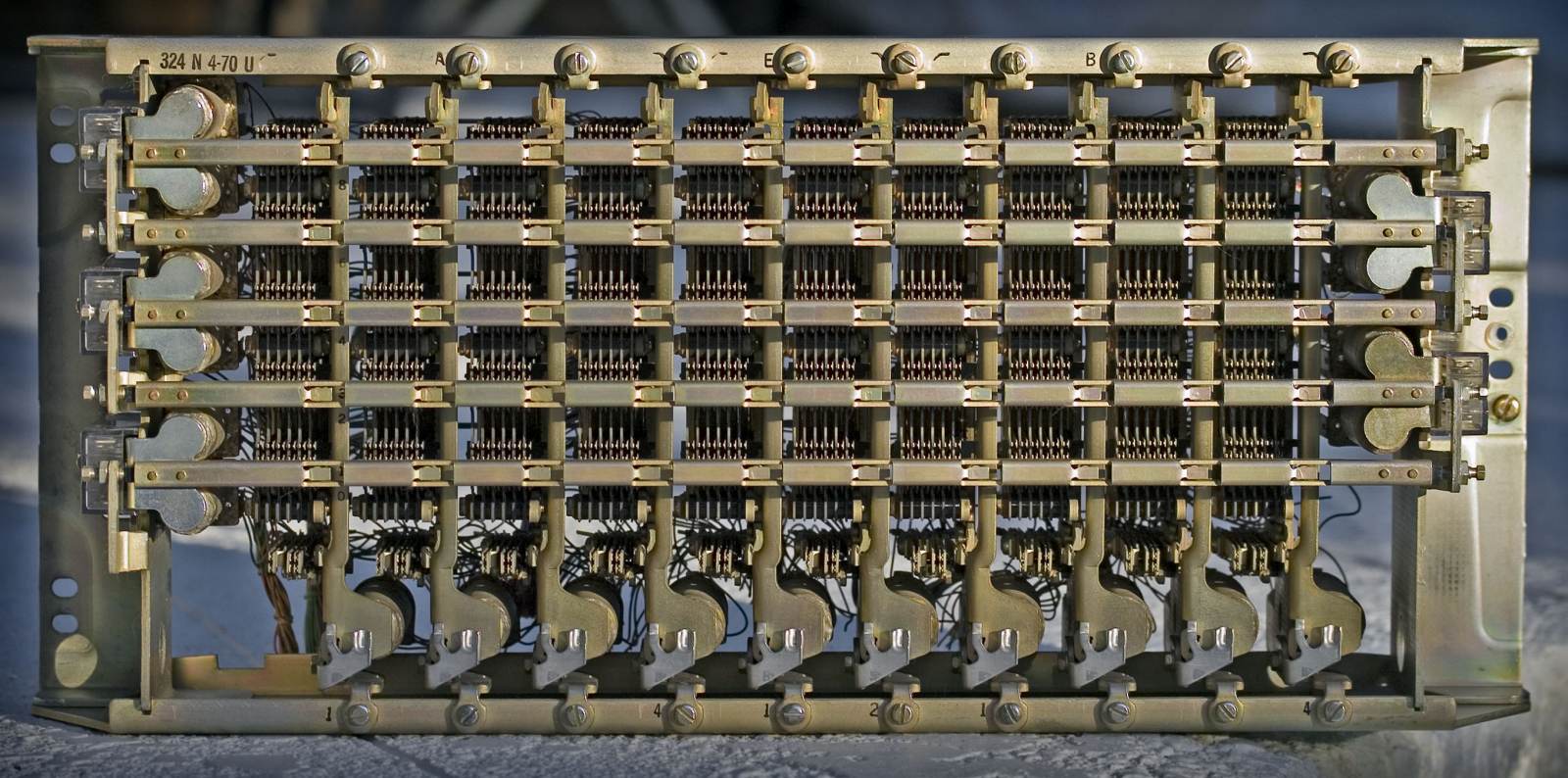
I’ll explain all the parts below, but for now notice the ten vertical bars with ten paddle shapes at the bottom. Hidden behind those ten paddles are ten solenoids (electro-magnets). These are the hold magnets that, as we’ll see, maintain a crosspoint connection.
Notice also the five horizonal bars and the double paddle shapes at their end. The first, middle, and last bars have these on the left, the second and fourth have them on the right. These are the select bars, and each paddle has a solenoid behind it — the select magnet.
In all cases, when a magnet is activated, it pulls the associated paddle towards it. In the first post, I listed the steps for closing a given crosspoint:
- Activate the select magnet for desired row.
- Activate the hold magnet for desired column.
- Release the select magnet.
The connection is maintained so long as the hold magnet is activated (hence the name; it holds the connection).
It may seem odd that there are ten vertical bars but only five horizontal bars. As we’ll see, the pair of select magnets associated with each select bar can cause it to rock up or down. So, there are ten hold magnets and ten select magnets.

The picture above shows a small part of a #5 Crossbar Switch. On the right is a rack (aka frame) of 10×20 crossbar switches. Recall from the first post that this allows a concentration of 20 input lines down to 10 output lines. These might concentrate 20 subscriber lines to 10 lines into the switch fabric — the idea being that not everyone uses the phone at the same time.
In fact, in some central offices, there can be more crossbar switches wired in common to create higher concentrations. Another set of 10×20 provides a 40:10 concentration. What is actually used in a given office depends on the expected traffic.
The middle frame shows some of the relays associated with the marker circuit. It has a 10×10 crossbar switch it uses as a register to hold information. The partially visible left frame is similar though note the relays above the crossbar are different — a different part of the marker logic.
Here is the best photo I could find of the back of a crossbar switch:
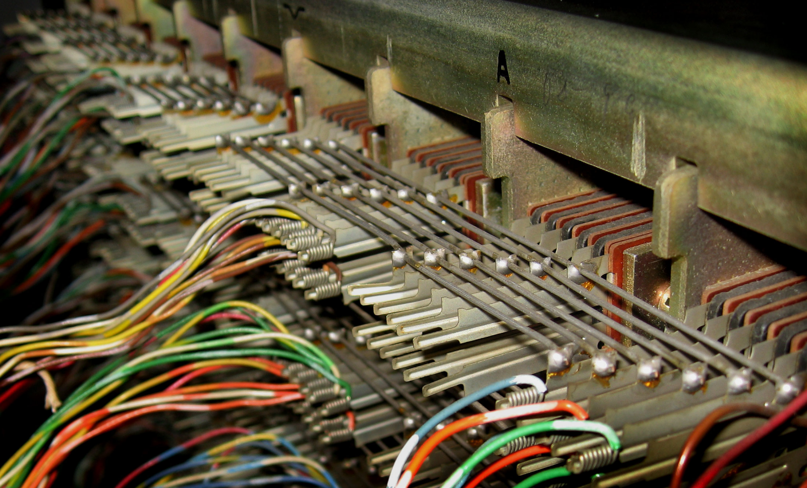
Of note are the six “banjo wires” from the lower right to the upper left. Note also how they connect four columns in the foreground, then break before connecting further columns in the background. This allows the crossbar to be divided for different purposes. The banjo wires on multiple crossbars can be wired together to create 10×30 or 10×40 (or more) crossbars. More typically, it’s how a 10×20 crossbar is divided into a pair of 10×10 switches — by cutting the banjo wires in the middle.
§
To illustrate how crossbar switches work, I created a 3D model in POV-Ray (the venerable 3D ray tracing application I’ve posted about before).
Here is the front:
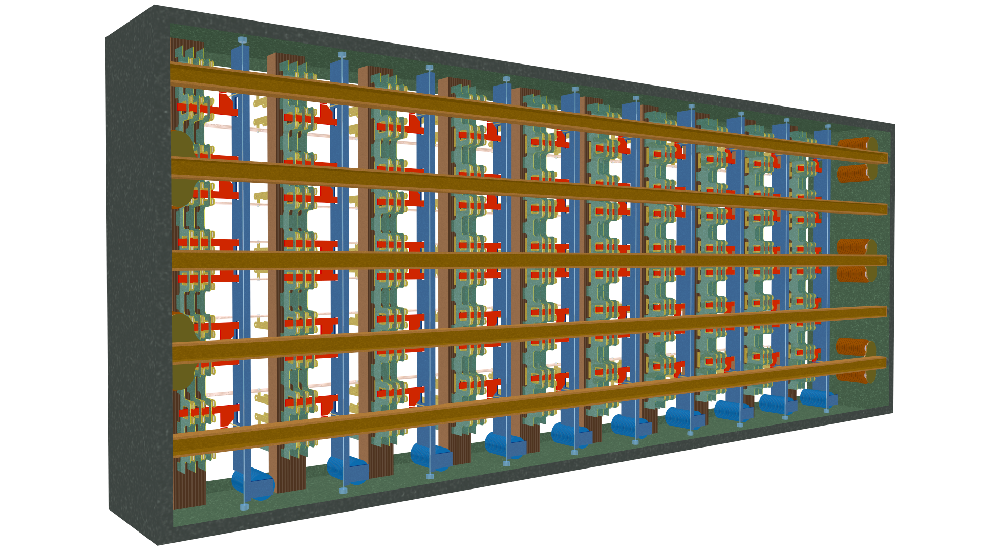
Note the five select bars (dark tan) and ten hold bars (blue). Visible to the far right are three pairs of select magnets. Visible across the bottom are the ten hold magnets (also blue).
Here is the back:
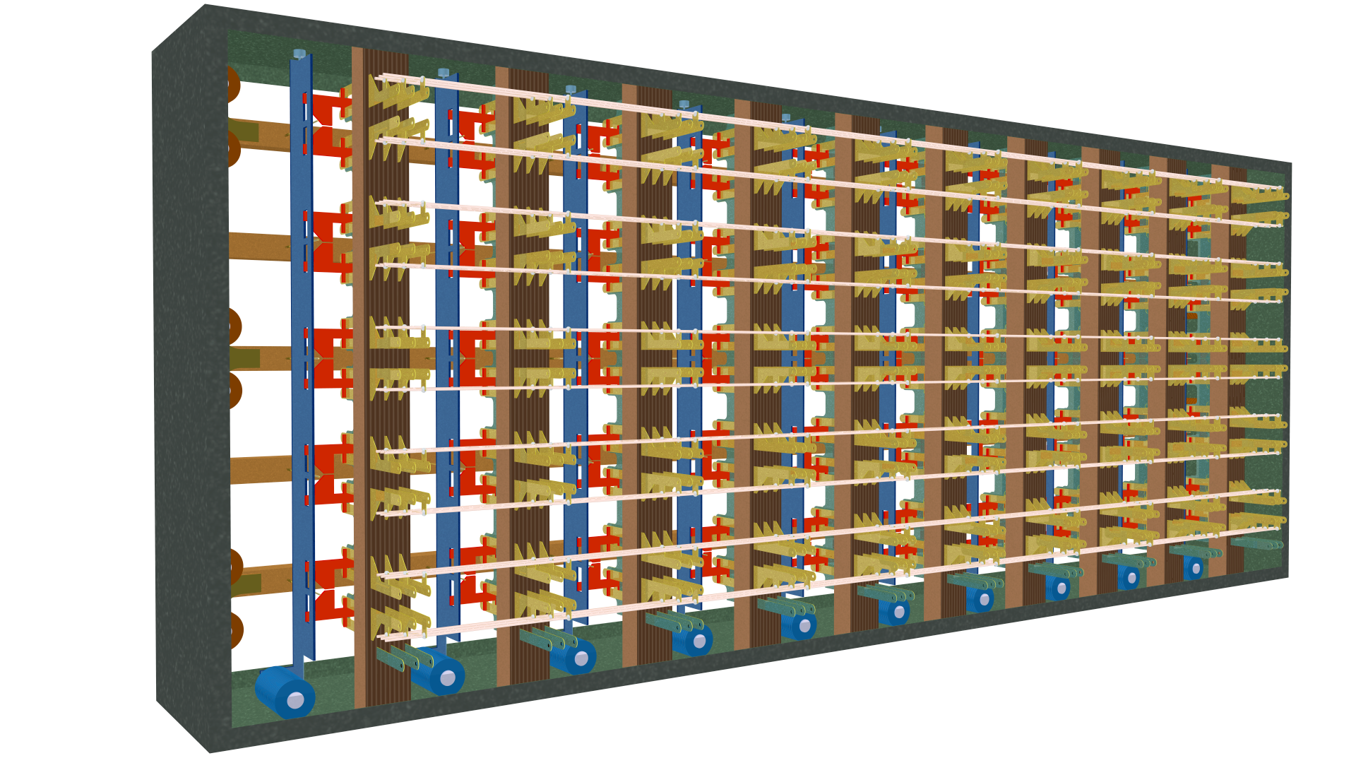
The hold magnets across the bottom are more visible here and note the banjo wires running horizontally. These connect the ten rows in all ten columns. Not visible is that the crosspoints in each column are electrically connected. Together, these create the crossbar pattern:
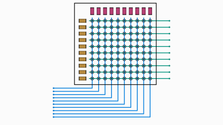
This diagram (from the first post) should make a bit more sense now. Across the top are the ten hold magnets (red). Across the left are the ten select magnets (tan). The banjo wires are the horizontal lines comprising the rows, and the vertical lines are the electrically common columns.
Remember that each line in the diagram above comprises three, four, or even six wires, depending on the type of crossbar. The more common are the three-wire type with the tip, ring, and sleeve lines discussed in the last two posts. Four-wire crossbars might switch full duplex lines with a tip and ring for each direction. Six-wire crossbars (such as the picture of the banjo wires above) might switch full duplex systems with tip, ring, and sleeve.
Here’s a closeup of the back of the crossbar:
Note the banjo wires connecting the rows. Each connects to one of the three conductors (gold) in each column. The gold tabs allow external connections into the switch fabric or to another crossbar. Because of the banjo wires, each of the three is connected to its matching tab in each column.
At the bottom are three green tabs that connect to the three conductors in the column.
Here’s another view from the bottom front:
The green tabs extend through the (non-conducting) column support and extend upwards to connect all ten crosspoints in the column. The gold tabs also extend through the support to one set of contacts on this side.
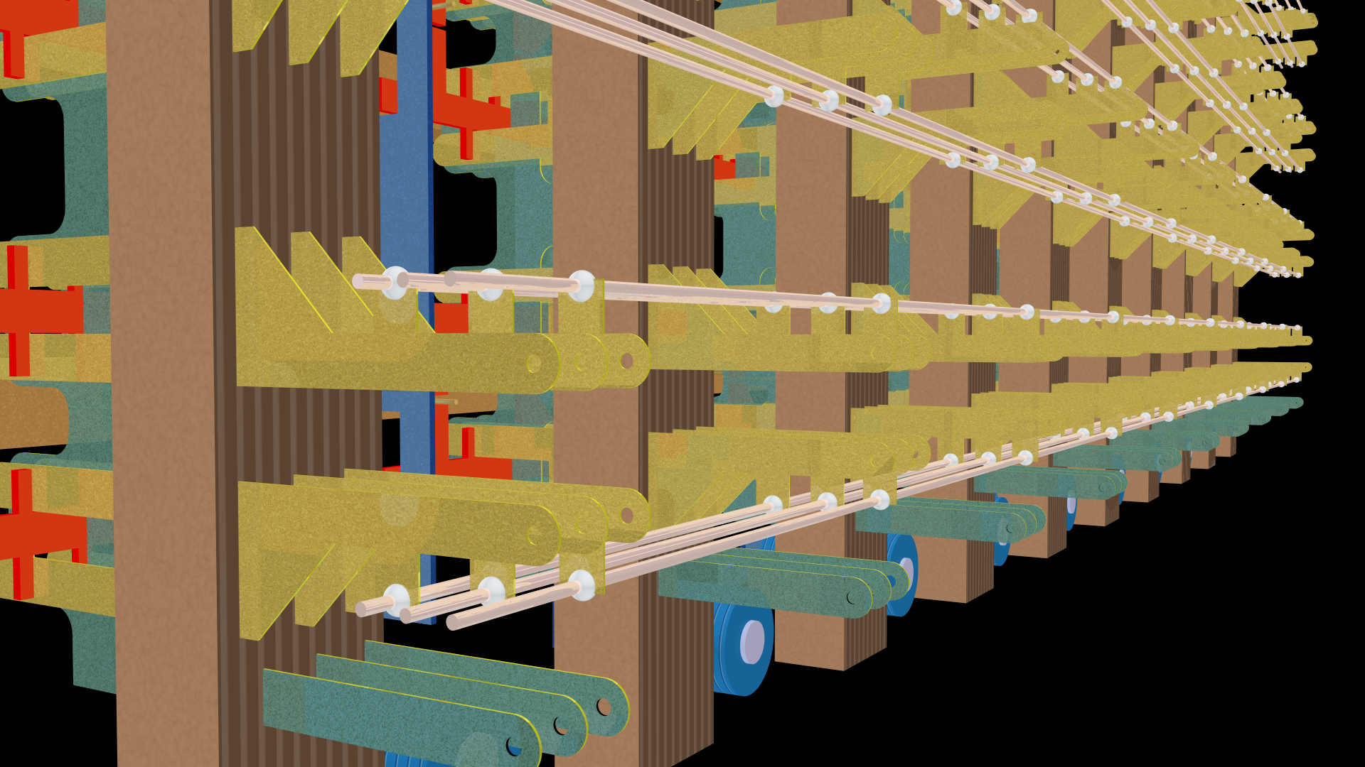
Here is another view from the side of the front showing two of the select bars running from foreground to background. Nestled among the blue vertical hold bars you can see bits of the green conductors that join the crosspoints in each column:
More importantly to the story, note the slender gold “fingers” extending to the right of each select bar.
Most importantly, note that each finger is mounted with a spring on the select bar. These springs allow the fingers to bend relative to the select bar. This is crucial to the crossbar operation.
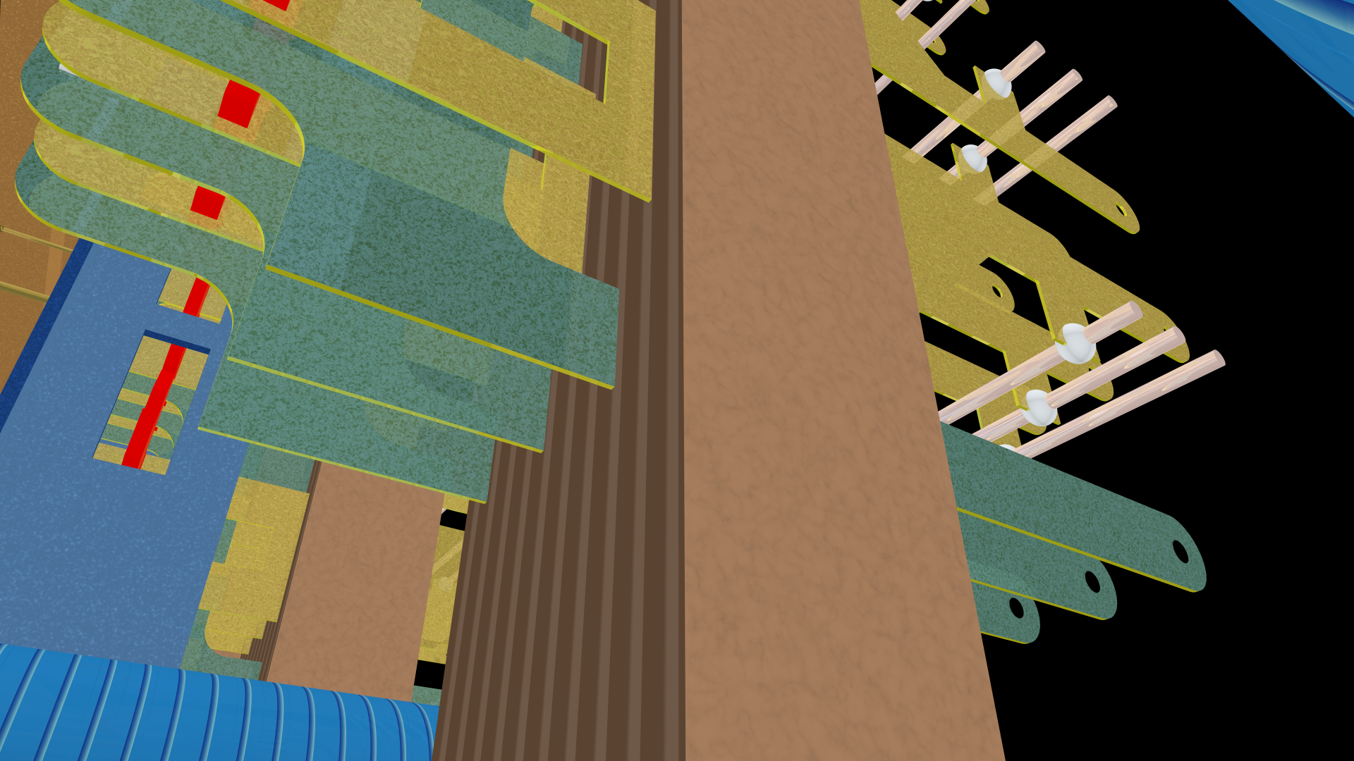
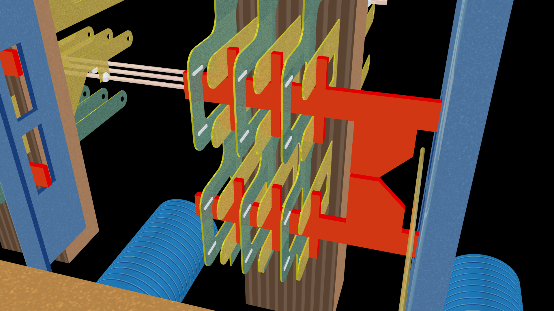
Here is an orthographic view of the back of the crossbar, lower-left corner:
It shows the bottom of three columns and the left of four rows. Note how the rows are paired, two to each horizontal select bar. On the far left, there are the two select magnets associated with the lower bar. The two select magnets for the upper bar are to the far right of the switch (and not shown here).
The banjo wires for the four rows run horizontally to the three conductors in each column. Along the bottom are the three hold magnets for the three vertical hold bars.
Note how the select bars and hold bars are mounted in bearings (small rectangular shapes) that allow them to pivot when an associated magnet activates.
Here is the same section of the crossbar from the front:
On each column support, note the three vertical conductors (gold) that join the tip, ring, and sleeve lines in each column.
Between the horizontal select bars and the vertical column supports are a set of red plastic “activation cards”. There are twelve such cards shown, one for each set of crosspoints. They are paired in mirror versions top and bottom along each select bar.
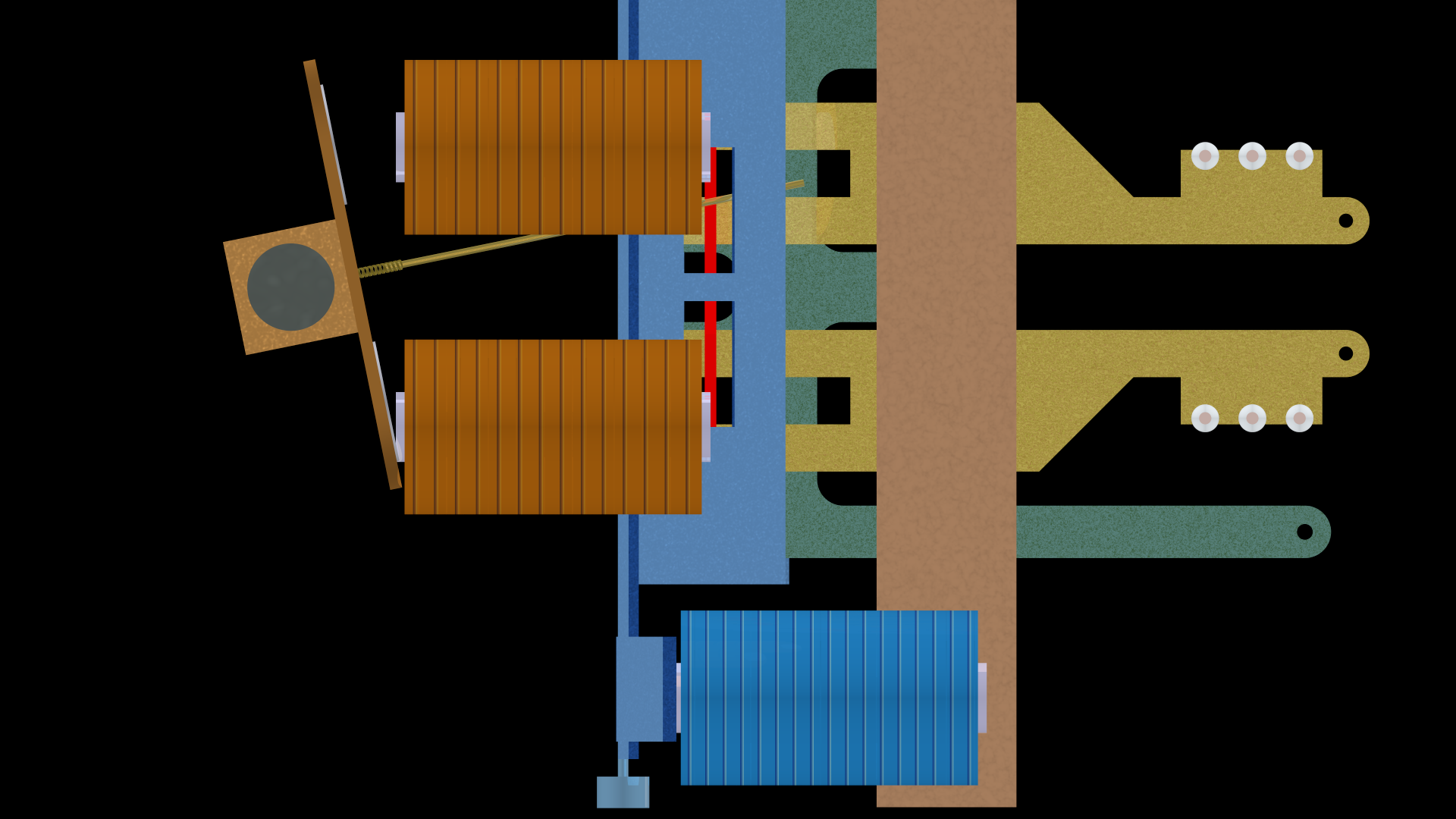
Here is a side view:
On the left are the two select bars seen end on, along with their paddles (seen edge on). To their right are four (and a half) select magnets, and at the bottom is the hold magnet (with nine more directly behind it).
On the lower right are the connection tabs for the vertical conductors. Above them are the tabs and banjo wires for the horizontal conductors.
Most importantly, note the blue vertical hold bar and the slots through it, one slot per row. Also note the select fingers extending from the select bar.
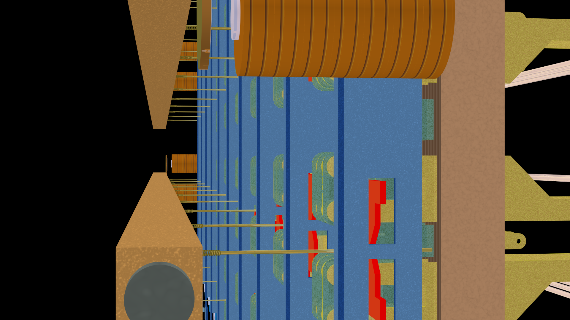
Lastly, here is a top view:
The select bar runs across the bottom with the select magnets in the lower right. The banjo wires run across the top. Note how they connect to three conductors at each crosspoint. The other three conductors are the common verticals connected to the green tabs seen above.
Together, there are three crosspoints (in fact actually 30 because each column has ten) with the red activation cards seen edge on (red). In this image, no crosspoints are active — none of the various conductors touch.
§
Now comes the cool part.
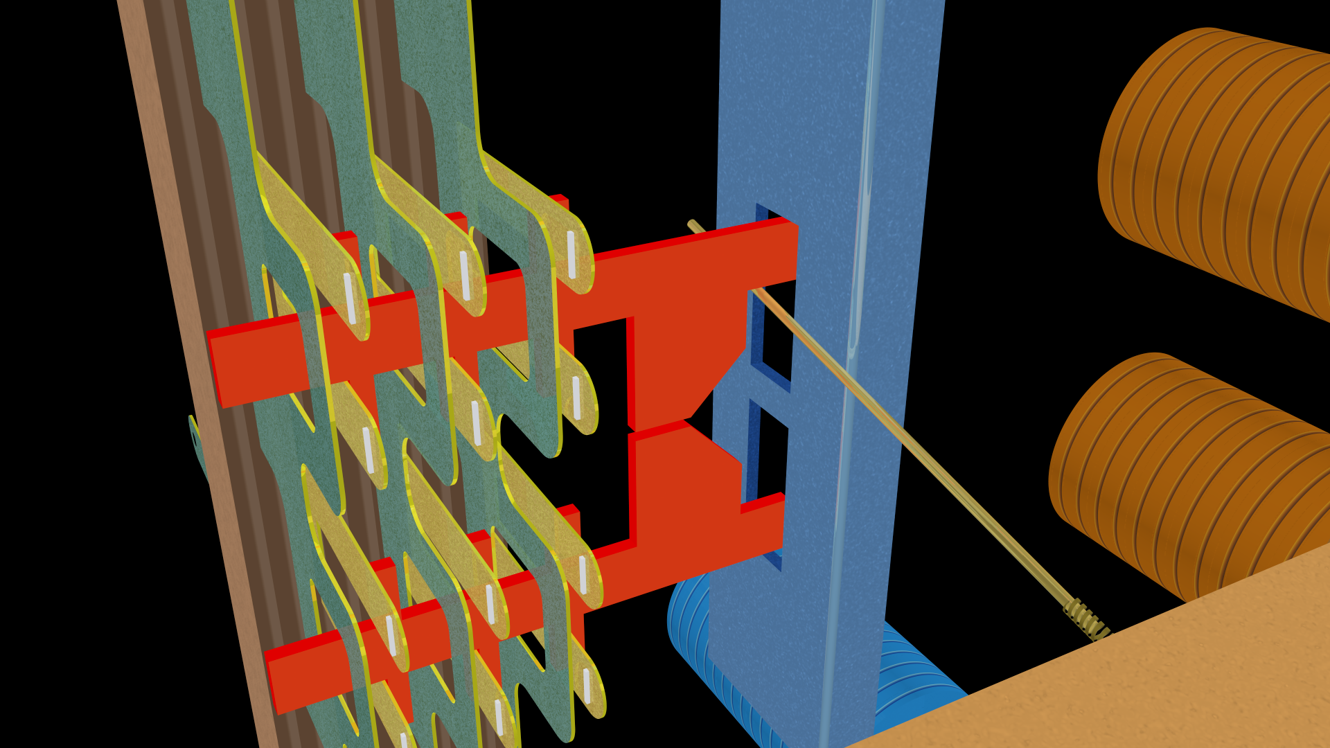
Recall that the first step in activating a crosspoint is to energize the select magnet for the desired row:
In the image above, the lower select magnet for a select bar is energized. This pulls the associated paddle towards it, thus tilting the select bar. Most importantly, the select fingers on that bar all rotate upwards.
In fact, energizing the lower magnet prepares the upper of the paired crosspoints for activation.
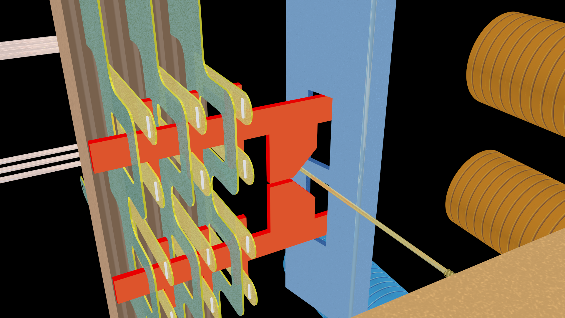
The second step is to energize the hold magnet for the desired column:
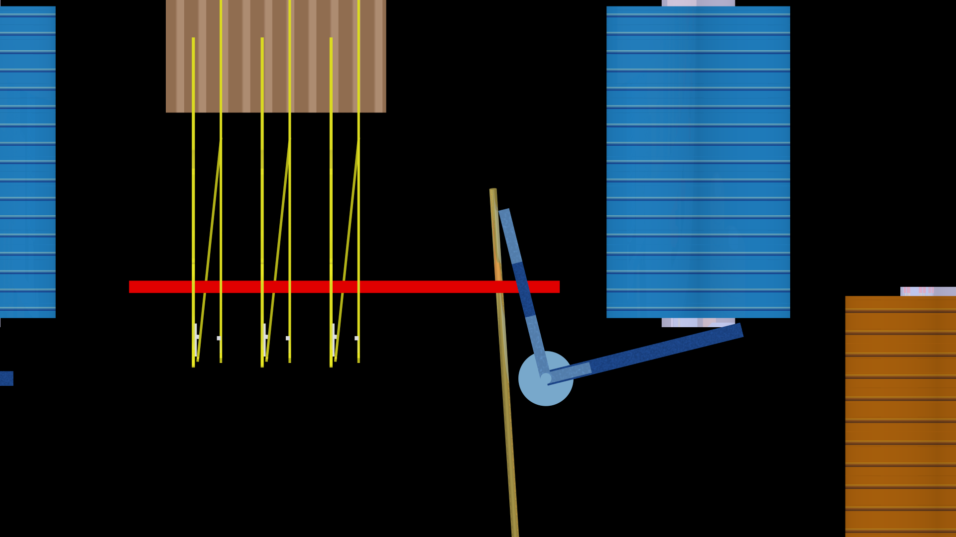
This pulls the paddle at the bottom of the hold bar towards the hold magnet, thus rotating the bar. Note how the select finger (extending from the bottom) is pushed to the left — it no longer sticks straight out (remember that it has a spring mount that allows rotation).
As we’ll see below, this pushes the associated activation card to the left, and this closes all three associated contacts, thus closing the crosspoint. Three of the row contacts now touch three of the column contacts.
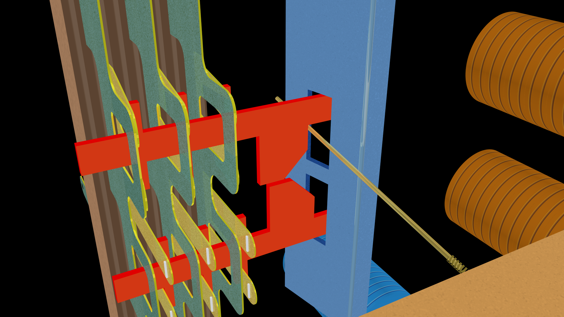
The third step is to release the select magnet to allow the select bar to return to its normal position but the specific select finger for the given crosspoint remains trapped by the hold bar, and this keeps the crosspoint activated so long as the hold magnet remains energized.
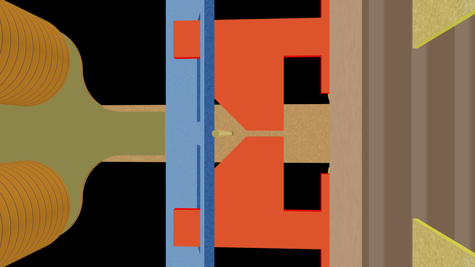
Here’s a closeup of the paired set of triple contacts:
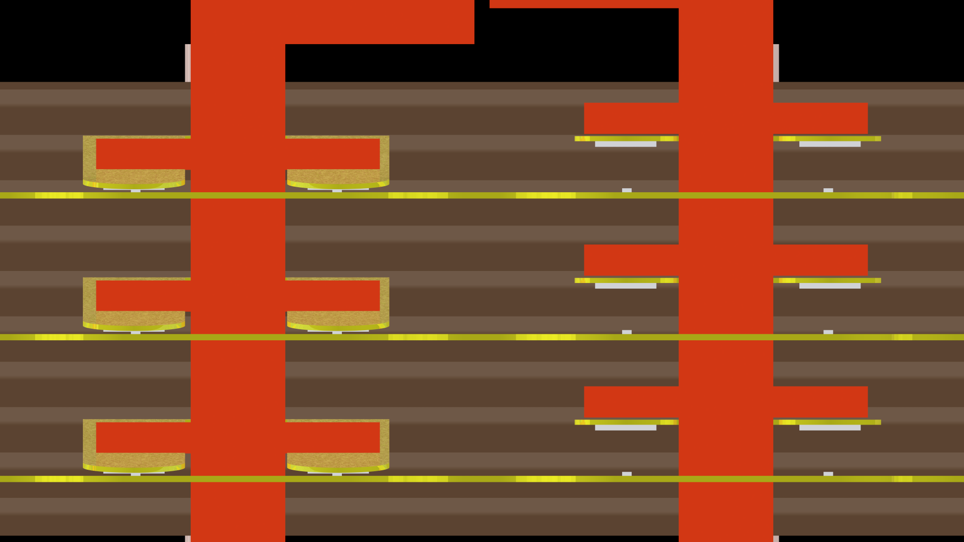
This image is rotated 90° to the left. The activated contacts, held closed by the activation card, are on the left. The crosspoint contacts on the right remain open — the activation card is in the normal position.
Note that each of the three contacts is paired — there are two contacts for each conductor. This helps ensure a good connection if one of the contacts is worn or dirty. Tiny bars of metal attached to the contacts meet in a cross and amplify the pressure by concentrating it in a very small area (not unlike spike heels amplify a person’s weight under the heel).
§
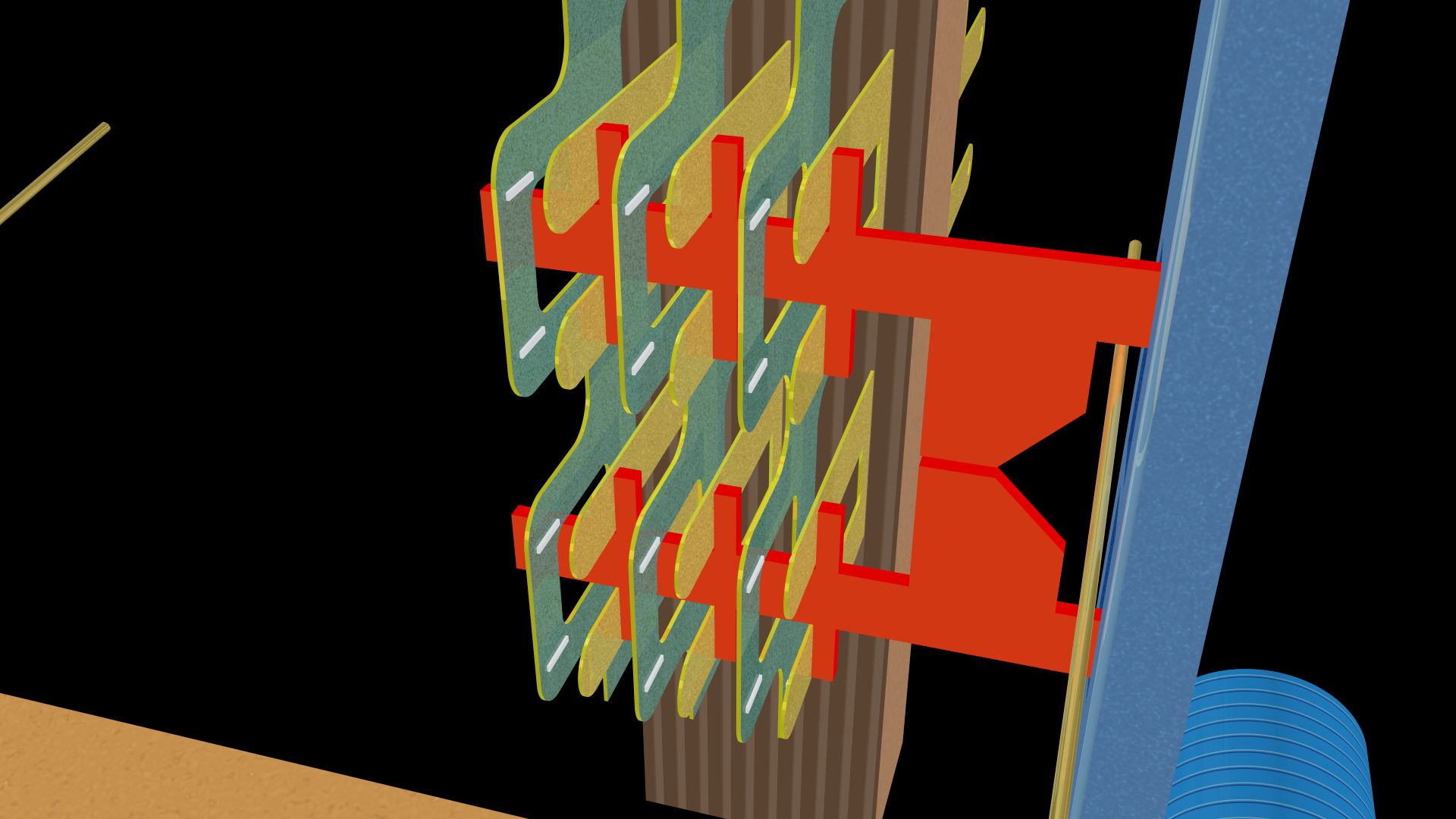
Let’s look at this in detail from four points of view. First, from the front left:
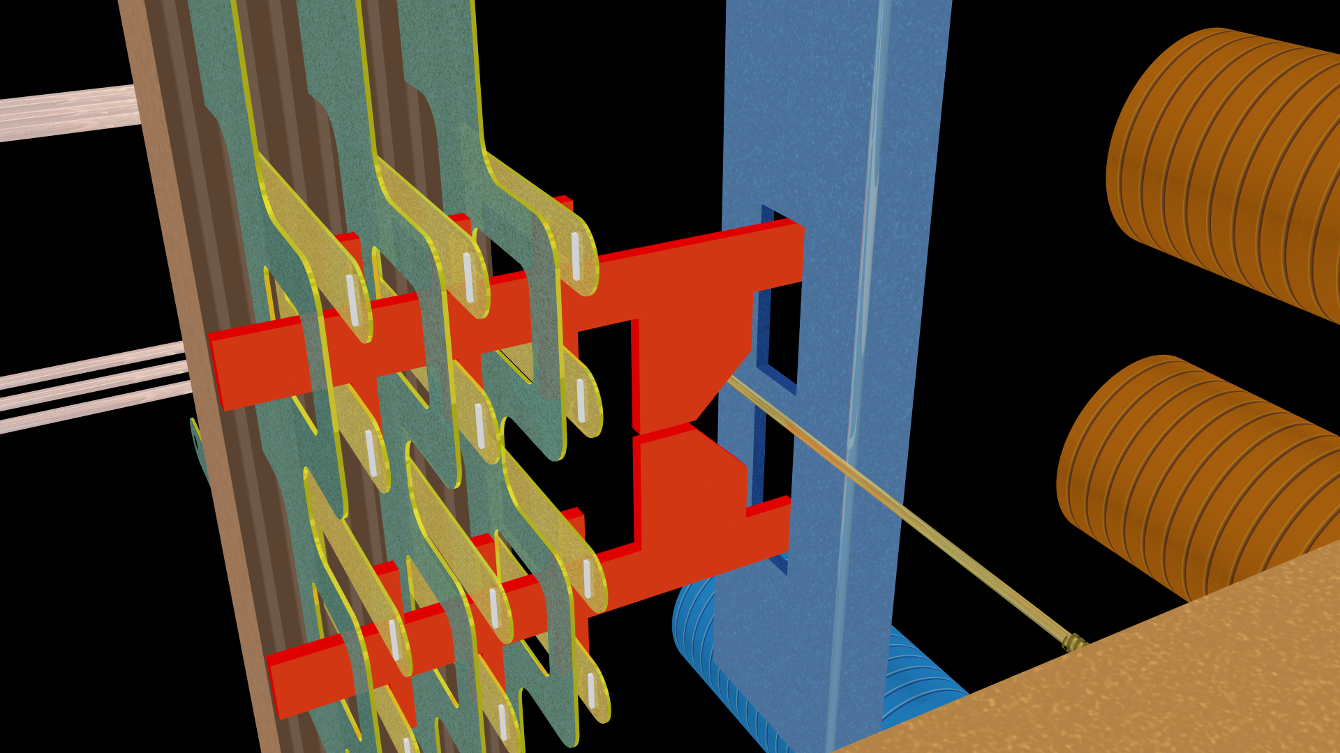
Above are a pair of crosspoints in the default position. The select finger is straight out from the select bar. None of the contacts touch. Note the tiny vertical bars of metal for each contact.
If the hold magnet was energized and the hold bar rotated, the select finger would be pushed into the “V” area between the two activation cards, thus leaving them in the default position:
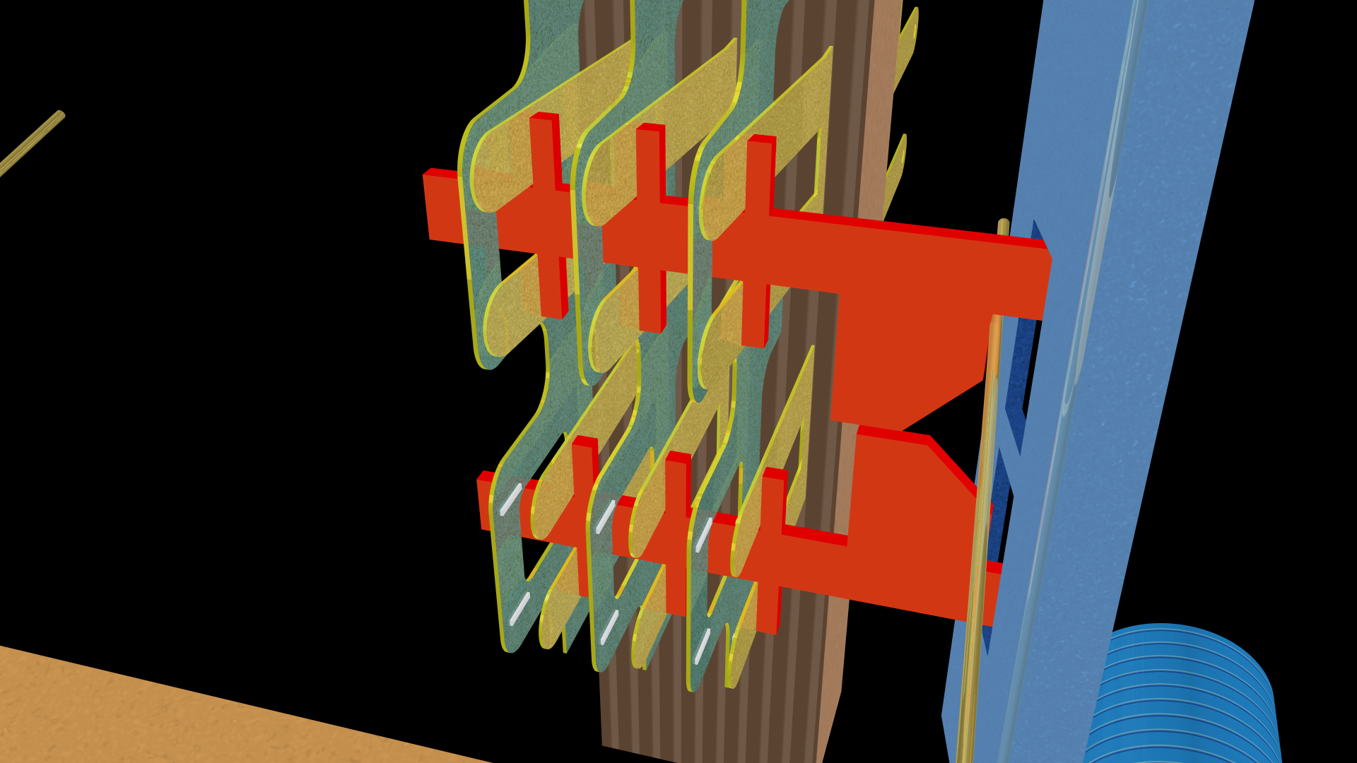
But because the lower select magnet tilts the select bar upwards:
The select finger is positioned against the activation card such that, when the hold bar is rotated, it pushes the activation card to the left (thus closing the associated contacts):
The select finger is now trapped between the hold bar and the activation card.
§
Here are the same three steps from the front right.
First, the default state:
The select bar is not rotated, and the select finger is straight out in the middle. (Here notice the tiny horizontal bars of metal for each contact. As mentioned, these meet the vertical bars to form a small-cross section area that comprises the actual electrical connection.)
Now we energize the select magnet to rotate the select bar:
The select finger moves upwards to land against the upper activation card.
Then we energize the hold magnet to rotate the hold bar:
Which pushes the select finger to the left against the activation card to close the upper set of contacts.
§
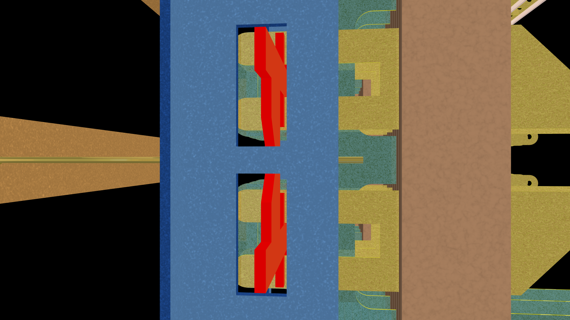
Here are the same three steps from the left looking through the slots in the hold bar. First, the default position:
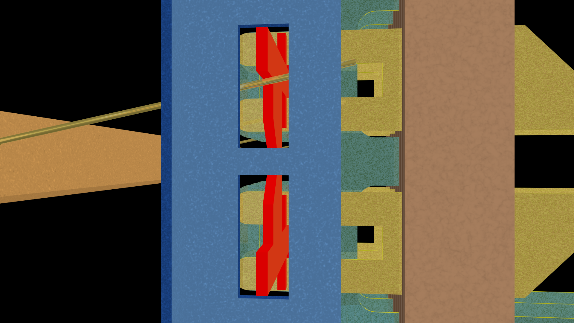
Now the select magnet rotates the select bar:
And then the hold magnet rotates the hold bar:
As an aside, the contacts are called “springs” because of how they flex and spring back when the pressure is removed (by releasing the hold magnet and thus the hold bar).
§
Lastly, the same three steps seen from the rear of the crossbar.
The default position:
The select bar rotated:
The hold bar rotated:
Here is another view of what happens when the select bar is not activated but the hold bar is:
The select finger moves into the “V” area, so neither activation card is moved, and neither set of contacts are closed.
[It was perhaps a bit of overkill showing the same thing four times, but I made the images, so I’m determined to use them. And this operation is the crux of the matter, so I wanted to make it as clear as possible.]
§
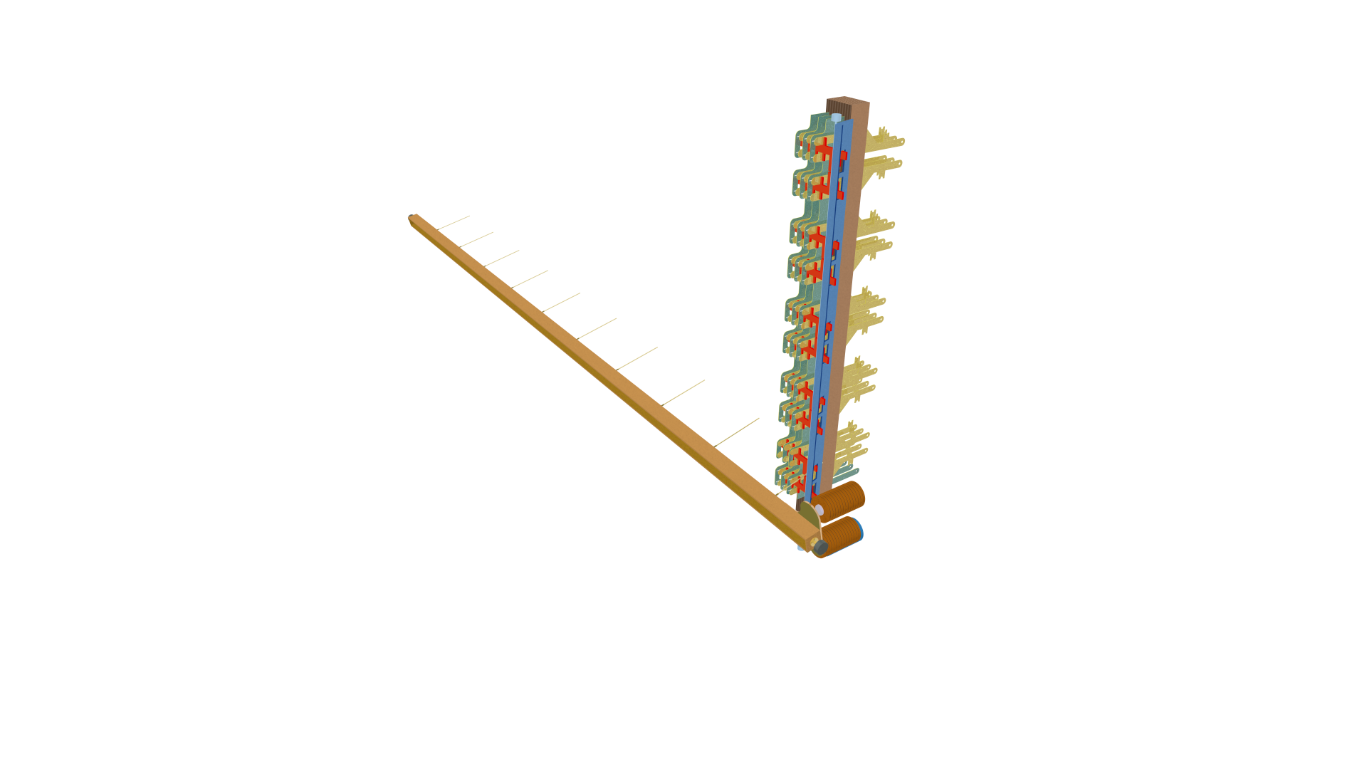
Speaking of using all the images I made, here’s one showing just one vertical column and one horizontal select bar (which serves a pair of contacts):
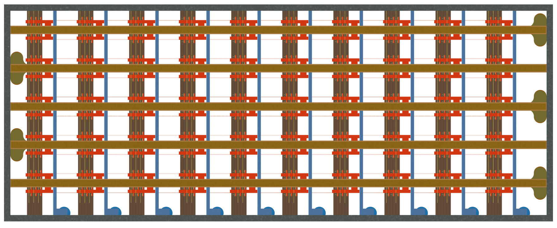
Lastly, orthogonal views of the whole crossbar from the front:
And the back:
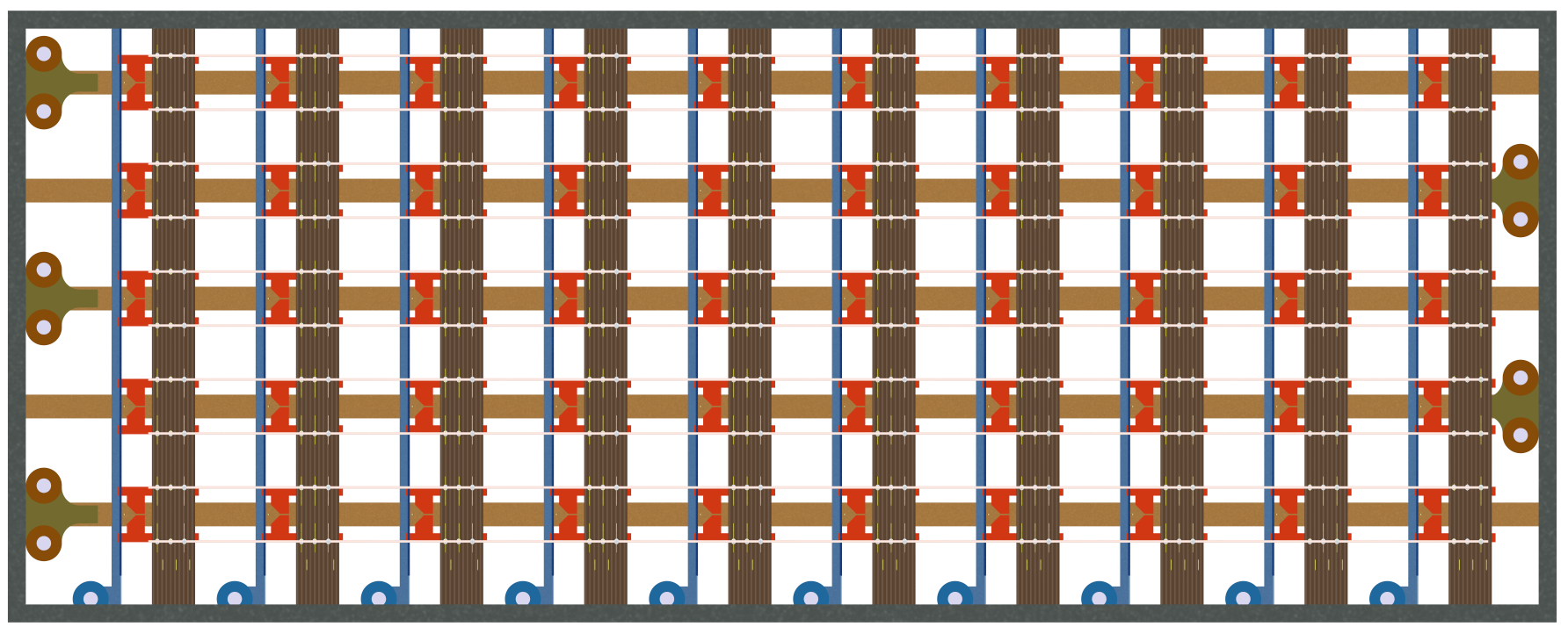
If you compare these with the photos of the real thing up top, you’ll see that I left a lot of space between things. That was (mostly) deliberate to make it easier to see what goes with what.
I also got the select bar paddles backwards. The three pairs should be on the left (as seen from the front), and the two pairs on the right. But these images come from my second attempt to create the model, and I didn’t have the heart to make it three.
§ §
And that’s a wrap. Any questions?
Stay switched, my friends! Go forth and spread beauty and light.
∇


April 27th, 2026 at 6:46 pm
I love your illustration in this post!
April 28th, 2026 at 11:29 am
Thank you! It was fun making the 3D model, and hopefully it helped make it clear how crosspoints work. (I’d like to believe that someday I’ll redo it more according to spec, but now that these posts are finally published, the odds of that are pretty close to zero. 😊)
May 15th, 2026 at 9:43 am
[…] has been a while — three weeks exactly — since the last post here. I haven’t been idle, though; quite the opposite. I reached three-score-and-ten last fall and […]