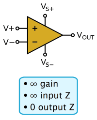
 The last Sideband post (over eight months ago) was about Op Amps, mostly because I think they’re very cool but also easy to understand in the context of the Three Rules of Op Amps. [See this post and maybe the one before it.]
I posted about them in part because I also wanted to post about an electronics project I designed (but never built) back in the late 1980s. I thought it was a cool solution that leveraged existing infrastructure and used off-the-shelf parts.
Be advised this post is seriously on the electronics geek side and is mainly a memory with meaning only to me. I used to love designing stuff!
A little background: The Company (TC) hired me as a Field Service Technician (FST) in Los Angeles (LA) but after four years offered me a transfer back to HQ (headquarters) to work in the National Service Center (NCS) assisting other FSTs around the country. I spent seven years there before I migrated into software. [See Reflections: Work & Change]
The NSC was divided into two “houses”. The larger one comprised minimally trained customer support call takers. They were able to help with basic customer issues and dispatch service techs. The smaller one — my house — was all former FSTs. We mainly supported field techs who’d run into a problem they couldn’t figure out. Sometimes we helped customers with more technical issues.
There was a desire for an “availability board” that let everyone know the status of everyone else. (This was back in the 1980s before computers automated that sort of thing.) The problem with a centralized board was the distance people would have to walk to change or even see it. Ideally, it should be near the receptionist who fielded calls for a specific individual. (The question being: is that person available to take a call.)
I designed a decentralized electronic system with multiple input modules that could be located near groups of call-takers as well as multiple display modules that could be placed as needed. It leveraged existing infrastructure and off-the-shelf parts. Even so, in retrospect, it was a bit ambitious. No surprise management didn’t go for it. (My imagination was still bigger than my common sense back then.)
That said, it was a cool design (for the day) and would have worked. This post memorializes that design. If you’ve actually read this far, feel free to bail. I don’t expect this to be of interest to anyone but me. (It’s a horribly obsolete design at this point.)
§ §
Back then we had a lot of Cat-5 (Category Five) cable in the walls, not all of it in use. My design took advantage of the unused cable. Cat-5 has four twisted pairs, three of which I used for data (one for signal, one for sync, one for clocking). The remaining pair was for backup in case one of the other pairs failed.
There was a single system clock (SysClock) module that provided timing for all other modules. (Click on any of the diagrams below for a full-sized version.)

Diagram 1a. System Clock module, part one of two (logic).
The design allowed tracking for 255 individuals. The SysClock provided a clock signal defining 256 “slots” — one of which was for synchronization (indicated by a separate sync signal). I estimated the system could cycle through all 256 slots many times per second.
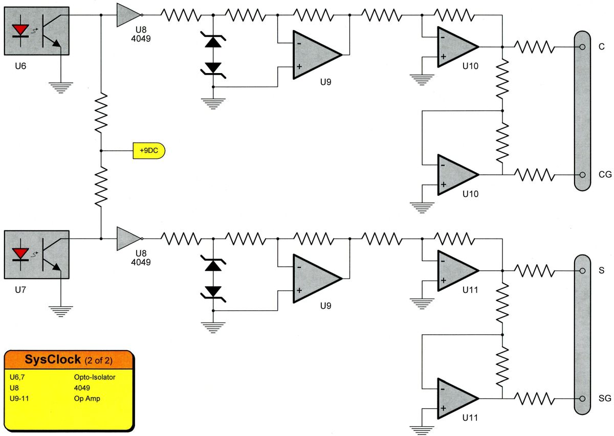
Diagram 1b. System Clock module, part two of two (NIF).
I used TTL for the logic and op-amps for the transmission and reception. Those required separate power supplies (+5 VDC and ±9 VDC), so I used opto-isolators to electronically isolate the two. In retrospect, I’d use a single bi-polar power supply.
I’ll say right now, this was over-designed. If I were to do it today, I’d take a more minimalist approach. This design rather suffers from my enthusiasm. For instance, in the SysClock (Diagram 1b), I wouldn’t bother with the middle signal conditioning part (the circuitry around the dual op-amp U9 component).
Actually, if I were to do it today, I wouldn’t use such an obsolete design at all. (And there would be no need for such a system, anyway. Times and technology have changed too much. Now the call system itself takes care of all this and more.)
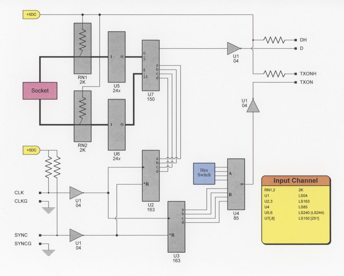
Diagram 2. Input module (up to 16 inputs).
The Input modules (where call-takers used a switch to indicate their availability) allowed for up to 16 people (with up to 16 modules possible). My intent was placing them at the end of every other row (each row had six to eight people). Call takers would thus have a short distance to walk — in most cases would walk right past the input panel on their way to or from their seat.
The Socket in Diagram 2 connected to the actual switch assembly, which was just a panel with (up to) 16 switches on it. One switch would be allocated to each call taker. The Hex Switch allowed configuring the module to one of 16 possible groups (0-15).
Note that the module configured for group #0 only supported 15 inputs because slot #0 of group #0 was the synchronization slot.

Diagram 3. Display module (as many as required).
The Display modules likewise supported 16 groups with 16 slots (minus group #0, slot #0). The Hex Switch again configures the module for a given group, but the Socket in this case leads to a display panel of some kind.
Which could be hefty (big lights) or minimal (little LEDs). The module just provided 16 signals that could be used as required.
This is, unfortunately, one place the design wasn’t very good. If there was to be a display showing everyone (say for the receptionist), it would require 16 modules. Or at least as many as required for all call-takers. We had about 80 people working there so seven groups would have more than covered us.
Other displays might have gotten away with showing just some of the groups — the customer call-takers really only needed to know about us technicians, and we didn’t really need to be aware of the customer call-takers availability. It was mainly the receptionist who needed the whole megillah.
Even so, it was a lot of electronics for the display. Far better to have used a simple CPU (like a Z80 or 6502) to control the display. (But that would have required EPROMs, and I designed under the KISS principle (Keep It Super Simple).
§
Diagram 2 and Diagram 3 just show the logic circuitry, the TTL part. Both Input and Display modules required network interfaces (NIFs). The Input modules needed to receive the clock and sync signals and transmit their data signals during their group interval. The Display modules needed to receive all three signals.
Diagram1b shows what the transmit NIF looked like. The Input modules had a similar circuit (with just one output rather than the two shown in Diagram 1b).
I never got around to making a nice Visio diagram of the receive NIF, but here is a drawing of the receive circuit (one required for each of data, clock, and sync):

Diagram 4. Receive NIF (two or three needed depending on module).
Again, some serious over-engineering there! The 10K potentiometer allowed compensating for network loss.
I later came up with a cleaner design:

Diagram 5. A cleaner (three-channel) NIF.
Even so, the design of the whole thing is a bit cringeworthy. While on one level I’m proud of the design, on another level I’m embarrassed. I record it here as something of a youthful folly.
In the above: D/DG are Data/Data Ground; C/CG are Clock/Clock Ground; and S/SG are Sync/Sync Ground. That’s on the TTL side. On the network side, the twisted pairs are balanced lines, so the signals are D+/D- and C+/C- and S+/S- (I mislabeled the network connections in Diagram 1b. They should be C+/C- and S+/S- rather than C/CG and S/SG. Oops!)
§
Just for grins, here is the drawing of the Input module:

Diagram 6. Drawing of an Input module. [Compare to Diagram 2.]
And here’s the drawing of the Display module:

Diagram 7. Drawing of a Display module. [Compare to Diagram 3.]
If you look closely, and compare them to the Visio diagrams, you’ll notice a hanging lead in about the center of each diagram (coming off the 1/6 U1 component). That was meant as a switch signal to connect the network outputs only when the group was active. Otherwise, the op-amp outputs would pull the network signal towards zero. I later came up with a design that didn’t need that, but that’s a topic for another Sideband.
§
Lastly, the design allowed for a star configuration:

Diagram 8. System in star configuration.
Or a linear configuration:

Diagram 9. System in linear configuration.
Depending on what worked best given final requirements and available wiring.
§ §
It was fun to design, but it’s just as well I never got the chance to implement it. It’s a workable design, but not a great one, even for the day. (It’s the reverse of when most engineers write software: it works but it’s usually a hard-to-maintain mess with lots of lurking gotchas.)
And, as I learned to my chagrin many years later, something this technical can often end up being a trap for the implementor. When I worked in the CRM group, I created some software that was very sophisticated and capable (and which I am still very proud of), but it trapped me in that department because no one else understood well enough to take it on. It took me three years to find and train a replacement so I could move on.
Mostly, I’ve looked back at this one as part of my ever-ongoing education. I did learn a lot. And certainly not the first nor last time a never-built design effort was a learning experience.
Stay balanced, my friends! Go forth and spread beauty and light.
∇


June 1st, 2023 at 11:33 am
Ha! One less post lurking in my Drafts folder. Been meaning to do this one for over a year.
June 1st, 2023 at 11:35 am
The original KISS principle was “Keep It Simple, Stupid” which I always found offensive. Who you callin’ stupid, stupid? Some places just dropped the final “S” but I like my version much better. Keeps the KISS without being offensive.
June 1st, 2023 at 11:38 am
As old Albert said, “It can scarcely be denied that the supreme goal of all theory is to make the irreducible basic elements as simple and as few as possible without having to surrender the adequate representation of a single datum of experience.”
Often paraphrased as, “Everything should be made as simple as possible, but no simpler.”
And in any event, really just Occam’s Razor.
June 1st, 2023 at 3:06 pm
It’s over my head, but congratulations on your design memorial!
June 2nd, 2023 at 11:40 am
Thanks! One more item on my TODO list checked off, and I can finally throw away the printouts and drawings.
It’s probably historical and largely forgotten now, but back in the day there was a famous comment in a bit of complicated core Unix code (the code bit dealt with task-switching, IIRC). It read, “You are not expected to understand this.” (So, even among the cognoscenti there are unfathomable depths!) I’ve long considered it a universal mantra — our islands of understanding are tiny in the vast sea of the unknown.
June 2nd, 2023 at 3:09 pm
I read as much as I could hoping I’d get a positive charge from your current post. However, my shocking shortage of electrical knowledge was too great a resistance.
June 3rd, 2023 at 11:13 am
😂🤣😂🤣 Well, I’m electrified that you even read this post! Nothing negative about that! 😉
June 2nd, 2023 at 9:03 pm
Very interesting insight on the trap of creating one’s own indispensability. Likely a hard lesson to learn, too, as it’s rather counterintuitive. It must have been fun revisiting your design and reliving that creative experience. I didn’t follow all of the technical details, but you still told a great story, and I enjoyed reading it!
June 3rd, 2023 at 11:20 am
Thanks! I’m impressed that you stuck with it. Good point about it being counterintuitive; it sure was for me. One just naturally wants to do their best, but (and what a shame) that can have unexpected consequences.
On the other hand, there’s an old saying about how much the corporation will miss you: Stick your hand in a pail of water. Now remove it. That hole you left in the water? That’s how much they’ll miss you. Even the clients who valued my work found they could move on. The hole closes pretty quickly!